
Solutions of Propylene Glycol and Water: An Analysis of Their Cutting parameters using CNC milling machine
- Raviteja Surakasi
- Ravi Ganivada
- Bobbadi Ushaswini
- 1942-1951
- Jun 20, 2024
- Education
Solutions of Propylene Glycol and Water: An Analysis of Their Cutting parameters using CNC milling machine
Raviteja Surakasi*, Ravi Ganivada, Bobbadi Ushaswini
Department of Mechanical Engineering, Lendi Institute of Engineering and Technology, Jonnada, Vizianagaram, Andhra Pradesh- 535005
*Correspondence Author
DOI: https://dx.doi.org/10.47772/IJRISS.2024.805140
Received: 30 April 2024; Revised: 13 May 2024; Accepted: 17 May 2024; Published: 20 June 2024
ABSTRACT
The primary goal of this study is to study the behavior of nanofluids containing graphene powder distributed in propylene glycol water when they are used as cutting fluids in the metal cutting process. Various nanofluids with compositions of 100:0, 75:25, and 50:50 were made from Propylene Glycol and Water. The workpiece made of aluminum is fixed to a CNC machine and a metal cutting process was done where nanofluids are used as cutting fluids. Several characteristics such as Arithmetic mean roughness (Ra), Root mean square roughness (Rq) and Ten Point height roughness (Rz) have been evaluated using the Taly surf apparatus, and cycle time is evaluated and it is found that with the increase in the depth of cut there is an increase in the value of cutting time and decrease in the values of Arithmetic mean roughness (Ra), Root mean square roughness (Rq) and Ten Point height roughness (Rz). It can be concluded that propylene glycol-water mixed in a ratio of 50:50can be used as cutting fluid in the metal cutting process.
Keywords: cycle time, Taly surf, arithmetic mean roughness, root mean square roughness, ten-point height roughness.
INTRODUCTION
As a 21st-century innovation, nanotechnology can alter numerous features of a material. Nanoparticles are emerging as a promising new addition for use in cooling systems. Recent progress in nanotechnology has included the creation of nanofluids. When it comes to movement and attributes, a particle is defined as a discrete unit. However, the size of ultrafine particles is between 1 and 100 nanometers. It is possible, but not certain, that nanoparticles will exhibit size-linked characteristics that significantly vary from those of tiny particles or complete materials. Due to its potential mechanical, biochemical, and electrical applications, research on nanoparticles is now a topic of high scientific relevance.
Over many decades, several fields have shown nanofluids’ usefulness. They may increase the heat transmission efficiency of industrial machinery. Since nanofluids came along, scientists have focused more on making them better at transferring and conducting heat than on making them less thick. When one or even more nanoparticles are spread throughout a base fluid, the resulting mixture is called a nanofluid.
A CNC milling machine is a versatile and precise tool used in modern manufacturing industries to create complex and precise parts and components. Unlike traditional milling machines, which require manual operation and adjustment, CNC milling machines are controlled by computer programs that allow for highly accurate and repeatable machining operations.
EXPERIMENTAL SETUP AND PROCEDURE:
CNC Milling machine:
A CNC milling machine is a versatile and precise tool used in modern manufacturing industries to create complex and precise parts and components. Unlike traditional milling machines, which require manual operation and adjustment, CNC milling machines are controlled by computer programs that allow for highly accurate and repeatable machining operations. Here are some features and components of a typical CNC milling machine:
Bed: The bed is the base of the machine that supports all other components. It is usually made of cast iron or steel and is designed to be rigid and stable to ensure accuracy during machining.
Spindle: The spindle is the rotating component of the machine that holds the cutting tool. It is typically driven by an electric motor and can rotate at high speeds, allowing for precise and efficient machining.
Cutting tool: A cutting tool is a rotating tool that is used to remove material from the workpiece. It is usually made of high-speed steel or carbide and is selected based on the specific material being machined and the desired surface finish.
Tool holder: The tool holder is the component that holds the cutting tool and attaches it to the spindle. It is designed to be easy to replace, allowing for quick tool changes and increased productivity.
Worktable: The worktable is the component that supports the workpiece during machining. It is typically adjustable in height, angle, and position, and may be equipped with various clamps and fixtures to hold the workpiece securely in place.
Control panel: The control panel is the interface between the operator and the machine. It typically consists of a computer screen, keyboard, and other input devices, and allows the operator to program and control the machine’s movements and operations.
CNC controller: The CNC (Computer Numerical Control) controller is the brain of the machine. It reads the operator’s instructions and converts them into electrical signals that control the machine’s movements and operations.
Axis system: The axis system is a set of linear or rotary motion components that control the machine’s movements along different directions. The most common axis system is a three-axis system, consisting of the X-axis (horizontal), Y-axis (vertical), and Z-axis (depth).
Coolant system: The coolant system is a component that cools and lubricates the cutting tool and workpiece during machining. It helps to prevent overheating and prolong the life of the cutting tool, and may also help to remove chips and debris from the work area. Figure 1 shows the CNC milling machine.
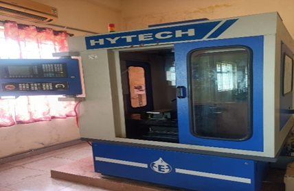
Figure 1: CNC Machine
Cutting Tools Used:
- Flat-end mill cutter:
A flat-end mill cutter is a tool used in milling machines to shape and cut various materials. It has a cylindrical body with a flat cutting edge at the end, which is often made of carbide. This cutting edge is used to create flat surfaces, slots, keyways, and other shapes in a workpiece. Flat-end mill cutters come in different sizes and can be used for both horizontal and vertical milling operations.
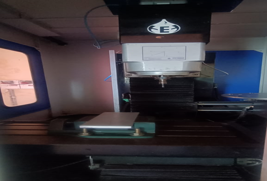
Figure 2: CNC Machine Bed and Tool setup (Flat End Mill cutter)
The flat-end mill cutter is an important tool for producing smooth finishes on workpieces, especially if the cutter is sharp and well-maintained. However, it has limited versatility in creating complex shapes due to its single-plane cutting edge. In such cases, other types of milling cutters with specialized cutting edges may be more appropriate. Overall, the flat-end mill cutter is a versatile and useful tool for a range of milling applications. Fig 2 shows the flat-end mill cutter.
Machine specifications:
- Model – SPM 250
- Controller- Siemens 808D
- Axis movement:
- x- 300 mm
- y-250 mm
- z-250 mm
- Axis motor and drive- SIEMENS V90
SERVO MOTOR WITH SERVO DRIVE
- Distance between tabletop and spindle nose – 70-370mm
- Distance between spindle to column- 270mm
- Feed rate – 0- 5000 mm/min
- Rapid travel – 5000mm/min
- Table size – 700 ×300mm
- Load on Table – 120 Kg
- Spindle motor capacity – 3HP
- Motor type- AC motor with VFD
- Spindle rpm- 100 to 3000 rpm
- type of magazine -Disc type
- Capacity of magazine – 8 tools
Taly surf Experimentation setup:
Specimen: The specimen is the surface that will be measured for roughness using the Talysurf apparatus. We have taken Aluminum specimens of 100mm×100mm which should be prepared by cleaning and removing any debris or contaminants.
Instrument: The Talysurf surface roughness apparatus is the main instrument used to measure the roughness of the specimen. It typically consists of a stylus that moves across the surface of the specimen, tracing its contours and recording roughness values. The instrument is calibrated before the experiment to ensure accurate readings. Fig 3 shows the Taly surf set
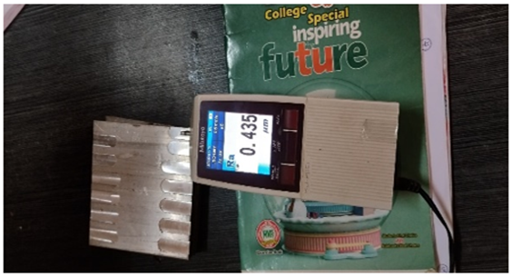
Figure 3: Taly Surf setup
EXPERIMENTAL PROCEDURE:
Experimental Procedure on CNC Milling:
- Select the appropriate cutting tool: Choose a cutting tool that is suitable for the material being machined and the size and shape of the slot to be cut. The tool should be securely mounted in the spindle.
- Position the workpiece: Mount the workpiece securely on the worktable and position it so that the slot is aligned with the cutting tool.
- Set the cutting parameters: Set the machine’s cutting parameters, such as the spindle speed, feed rate, and depth of cut. These parameters will depend on the material being machined and the size and shape of the slot.
- Enter the Program: Create a program using G and M codes in edit mode, that instructs the machine to cut the slot. This program will include the cutting path, cutting parameters, and any other instructions necessary to complete the operation.
- Start the machine: Put auto mode control the rapid rate and feed rate with 100% and press the cycle start button once. Now the machine will run. The cutting tool will move along the designated path, removing material from the workpiece to create the slot.
- Monitor the process: Keep an eye on the machining process to ensure that everything is running smoothly. Check the workpiece periodically to ensure that the slot is being cut to the correct dimensions.
- Finish the slot: Once the slot has been cut to the desired depth and width, stop the machine and remove the workpiece. If necessary, use pressurized air to remove the chips.
- Clean up: Clean up the work area and return the machine and cutting tool to their proper storage locations. Fig 4 shows the workpiece which is machined using a CNC milling machine.
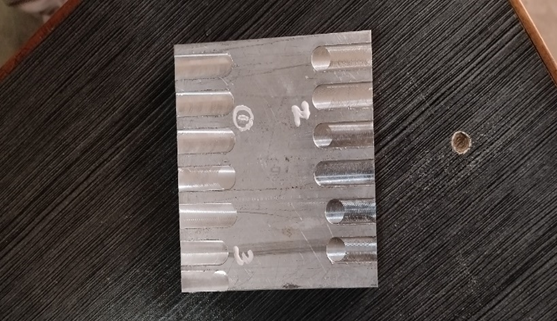
Fig 4: Aluminum plate after Flat cutting using CNC
PROGRAM:
O123;
N1 G75 Z0;
N2 T5 D1 M6;
N3 M03 S250;
N4 G54 G90 G17 G00 X8 Y-10;
N5 G00 Z3;
N6 G01 Z-0.2 F200;
N7 G01 X25 Y-10;
N8G01 Z0.5;
N9 G00 Z50;
N10 G75 Z0;
N11 G75 Y0;
N12 M30;
Experimental Procedure on Tally Surf Apparatus:
- The power supply to the tally surf measuring instrument and given its checked with the reference sample for the roughness.
- The instrument is bound on the specimen properly and then the measurement is stored by pressing the start/stop button. Note down Ra, Rq&Rz values using the parameter button.
- Repeat the experimentationof the specimen by changing the distribution.
- Repeat the process for the remaining specimen and tabulate the readings.
RESULTS
Depth of cut vs cutting force in X-direction:
Figure 5 represents the graph between the Depth of cut and cutting force in the X-direction for different proportions of propylene glycol and water. In this evaluation, we observe that Cutting force in X-direction increases with increasing the depth of cut. These results demonstrate an increase in the cutting force with increasing the water percentage in the sample. Sample PG + Water (50:50) has better-cutting force.
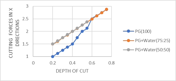
Figure 5: Graph drawn between Depth of cut vs cutting force in X- direction for different proportions of propylene glycol and water
Depth of cut vs Cutting force in Y-direction:
Figure 6 represents the graph between the Depth of cut and cutting force in the Y-direction for different proportions of propylene glycol and water. In this evaluation, we observe that Cutting force in Y-direction increases with increasing the depth of cut. These results demonstrate an increase in the cutting force with increasing the water percentage in the sample. Sample PG + Water (50:50) has better-cutting force.
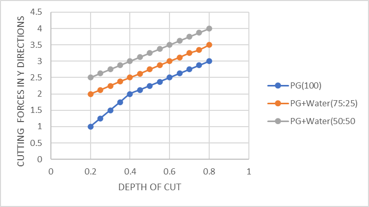
Figure 6: Graph is drawn between Depth of cut vs cutting force in Y-direction for different proportions of propylene glycol and water
Depth of cut vs cutting force in Z-direction:
Figure 7 represents the graph between the Depth of cut and cutting force in the Z-direction for different proportions of propylene glycol and water. In this evaluation, we observe that Cutting force in Z-direction increases with increasing the depth of cut. These results demonstrate an increase in the cutting force with increasing the water percentage in the sample. Sample PG + Water (50:50) has better-cutting force.
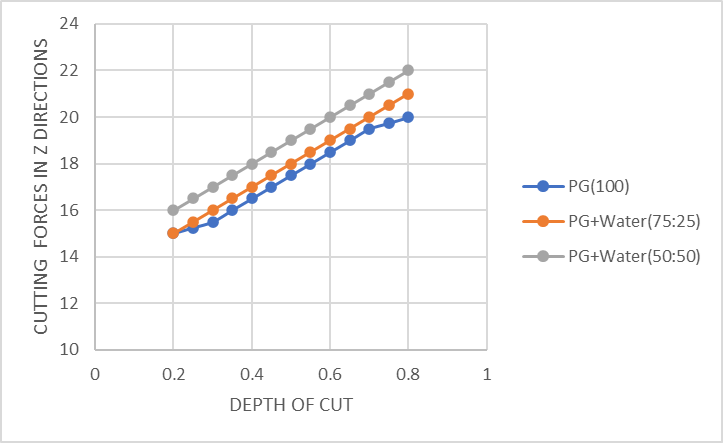
Figure 7: Graph is drawn between Depth of cut vs cutting force in Z-direction for different proportions of propylene glycol and water
Depth of cut vs Arithmetic mean roughness Ra:
Figure 8: Graph drawn between Depth of cut vs Arithmetic mean roughness, Ra for different proportions of propylene glycol and water.In this evaluation, we observe that Arithmetic mean roughness decreases with increasing the depth of cut and Ra increases with increasing water percentage in the samples. These results demonstrate an increase in the Arithmetic mean roughness with increasing the water percentage in the sample. Sample PG + Water (50:50) has better Arithmetic mean roughness.
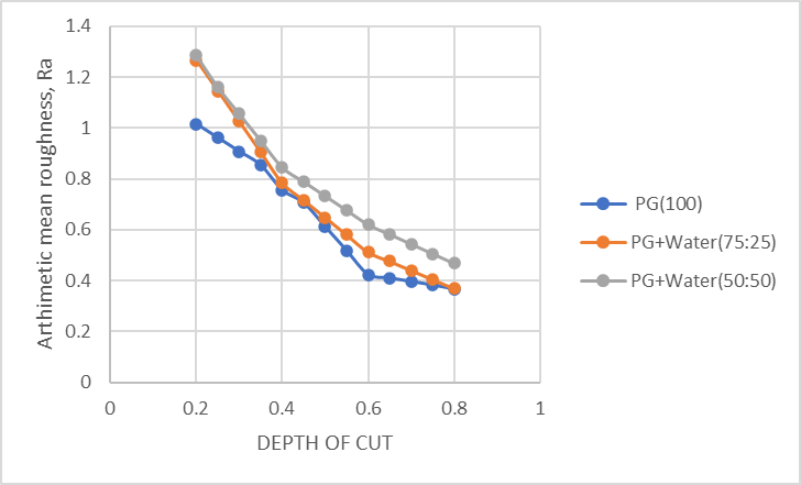
Figure 8: Graph drawn between Depth of cut vs Arithmetic mean roughness, Ra direction for different proportions of propylene glycol and water
Depth of cut vs Root mean square roughness Rq:
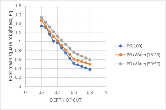
Figure 9: Graph is drawn between Depth of cut vs Root mean square roughness, Rq direction for different proportions of propylene glycol and water
Figure 9: Graph is drawn between Depth of cut vs Root mean square roughness, Rq for different proportions of propylene glycol and water. In this evaluation, we observe that Root mean square roughness decreases with increasing the depth of cut and Rq increases with increasing water percentage in the samples. These results demonstrate an increase in the Root mean square roughness with increasing the water percentage in the sample. Sample PG + Water (50:50) has better Root mean square roughness.
Depth of cut vs Ten-point higher roughness, Rz:
Figure 10: Graph is drawn between Depth of cut vs Ten-point higher roughness, Rz for different proportions of propylene glycol and water.In this evaluation we observe that Ten-point higher roughness decreases with increasing the depth of cut and Rz increases with increasing water percentage in the samples. These results demonstrate increase in the Ten-point higher roughness with increasing the water percentage in the sample. Sample PG + Water (50:50) has better Ten-point higher roughness.
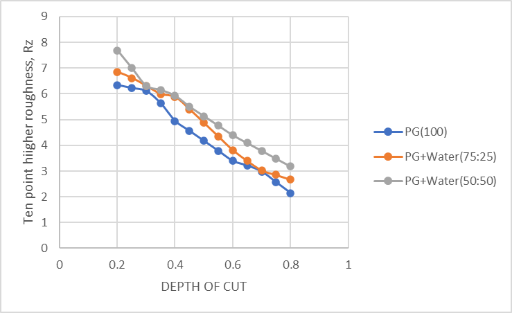
Figure 10: Graph is drawn between Depth of cut vs Ten point higher roughness, Rz direction for different proportions of propylene glycol and water
SUMMARY:
- For this study we prepare the samples which are having different proportions of Propylene glycol and water and we evaluate the cutting parameters and surface roughness.
- In this evaluation Cutting parameters in X, Y, and Z directions are increased with increasing depth of cut and also increasing the water percentage in the sample. Sample PG + Water (50:50) has better-cutting parameters.
- In this evaluation Arithmetic mean roughness, Ra decreases with increasing depth of cut and increases with increasing the water percentage in the samples. And sample PG + Water (50:50) has better Arithmetic mean roughness.
- In this evaluation Root mean square roughness, Rq decreases with increasing depth of cut and increases with increasing the water percentage in the samples. And sample PG + Water (50:50) has better Root mean square roughness.
- In this evaluation Ten-point higher roughness, Rz decreases with increasing depth of cut and increases with increasing the water percentage in the samples. And sample PG + Water (50:50) has a better Ten-point higher roughness.
REFERENCES
- Baby, T.T., Ramaprabhu, S. Enhanced convective heat transfer using graphene dispersed nanofluids. Nanoscale Res Lett 6, 289 (2011). https://doi.org/10.1186/1556-276X-6-289
- Murshed, S. M. S., K. C. Leong, and C. Yang. “Thermophysical and electrokinetic properties of nanofluids–a critical review.” Applied thermal engineering 28.17-18 (2008): 2109-2125.
- Leena, М., Srinivasan, S. Experimental Investigation of the Thermophysical Properties of TiO2/ Propylene Glycol–Water Nanofluids for Heat-Transfer Applications. J Eng Phys Thermophy 91, 498–506 (2018). https://doi.org/10.1007/s10891-018-1770-7
- Raviteja Surakasi, K. Ch. Sekhar, Ekrem Yanmaz, G. Yuvaraj, Jayaprakash Venugopal, S. Srujana, Naziya Begum, “Evaluation of Physicothermal Properties of Silicone Oil Dispersed with Multiwalled Carbon Nanotubes and Data Prediction Using ANN”, Journal of Nanomaterials, vol. 2021, Article ID 3444512, 11 pages, 2021. https://doi.org/10.1155/2021/3444512
- Surakasi, R., Sekhar, K.C., Kavitha, E. et al. Evaluation of physico-thermal properties of TiO2–water mixture dispersed with MWCNTs. Nanotechnol. Environ. Eng. 7, 325–331 (2022). https:// doi.org/ 10. 1007/s41204-022-00242-4
- Raviteja Surakasi, Srujana Sripathi, Sarada Purnima Nadimpalli, Sibtain Afzal, Bharat Singh, Manoj Tripathi, Rahel Alemu Hafa, “Synthesis and Characterization of TiO2-Water Nanofluids”, Adsorption Science & Technology, vol. 2022, Article ID 3286624, 9 pages, 2022. https:// doi.org/ 10.1155/ 2022/ 3286624
- Ch. Sekhar, Raviteja Surakasi, ilhan Garip, S. Srujana, V. V. Prasanna Kumar, Naziya Begum, “Evaluation of Physicothermal Properties of Solar Thermic Fluids Dispersed with Multiwalled Carbon Nanotubes and Prediction of Data Using Artificial Neural Networks”, Journal of Nanomaterials, vol. 2021, Article ID 7306189, 13 pages, 2021. https://doi.org/10.1155/2021/7306189
- Haribabu, A., Surakasi, R., Thimothy, P. et al. Study comparing the tribological behavior of propylene glycol and water dispersed with graphene nanopowder. Sci Rep 13, 2382 (2023). https://doi.org/ 10. 1038/s41598-023-29349-7
- Qingan, Y.; Changhe, L.; Lan, D.; Xiufang, B.; Yanbin, Z.; Min, Y.; Dongzhou, J.; Yali, H.; Yonghong, L.; Runze, L. Effects of the physicochemical properties of different nanoparticles on lubrication performance and experimental evaluation in the NMQL milling of Ti–6Al–4V. Int. J. Adv. Manuf. Technol. 2018, 99, 3091–3109.
- Kumar, M.S.; Krishna, V.M. An Investigation on Turning AISI 1018 Steel with Hybrid Biodegradeable Nanofluid/MQL Incorporated with Combinations of CuO-Al2O3 Nanoparticles. Mater. Today Proc. 2020, 24, 1577–1584.
- Surakasi, G. C. Sekhar, J. Pakalapati, R. Pakalapati, and M. Rafeeq, “Evaluation of electrical properties of graphene nanopowder-dispersed propylene glycol-water solutions,” Engineering Research Express, vol. 5, no. 3, p. 035019, Jul. 2023, https://doi.org/10.1088/2631-8695/ace58e
- Surakasi, R., Sekhar, K.C., Kavitha, E. et al. Evaluation of physico-thermal properties of TiO2–water mixture dispersed with MWCNTs. Nanotechnol. Environ. Eng. 7, 325–331 (2022). https:// doi. org/ 10. 1007/s41204-022-00242-4
- Teja, C. Sekhar, S. Ramam, B. Rao, and Ushaswini, “The Combustion and Emission Characteristics of Corn Oil Biodiesel with Titanium Oxide (TiO2) Nano-additive,” Journal of Environmental Nanotechnology, vol. 13, no. 1, pp. 97–103, Mar. 2024, doi: https:// doi.org/ 10. 13074/ jent. 2024. 03. 241512.
- Janaki, Raviteja, Deepthi, A. Kumar, D. Prasad, and B. Rao, “Evaluation of Dielectric Properties of Peanut Oil Biodiesel Mixed with Nano-additives,” Journal of Environmental Nanotechnology, vol. 13, no. 1, pp. 111–116, Mar. 2024, doi: https://doi.org/10.13074/jent.2024.03.241514.
- Surakasi, R. Ganivada, and R. Pakalapati, “Study Comparing the Tribological Behavior of Cottonseed and Castor Oil Biodiesel Blended Lubricant under varying Load Conditions,” International Journal for Research in Applied Science and Engineering Technology, vol. 11, no. 4, pp. 4047–4055, Apr. 2023, doi: https://doi.org/10.22214/ijraset.2023.51178.
- Kumar, M.S.; Krishna, V.M.; Varun, A. Investigation on influence of Hybrid Biodegradable Nanofluids (CuO-ZnO) on Surface Roughness in Turning AISI 1018 Steel. Mater. Today Proc. 2020, 24, 1570–1576.
- Majak, D.; Olugu, E.U.; Lawal, S.A. Analysis of the effect of sustainable lubricants in the turning of AISI 304 stainless steel. Procedia Manuf. 2020, 43, 495–502. Gong, L.; Bertolini, R.; Ghiotti, A.; He, N.; Bruschi, S. Sustainable turning of Inconel 718 nickel alloy using MQL strategy based on graphene nanofluids. Int. J. Adv. Manuf. Technol. 2020, 108, 3159–3174.
- Singh, H.; Sharma, V.S.; Dogra, M. Exploration of graphene assisted vegetables oil based minimum quantity lubrication for surface grinding of TI-6AL-4V-ELI. Tribol. Int. 2020, 144, 106113.
- Ibrahim, A.M.M.; Li, W.; Xiao, H.; Zeng, Z.; Ren, Y.; Alsoufi, M.S. Energy conservation and environmental sustainability during grinding operation of Ti–6Al–4V alloys via eco-friendly oil/graphene nano additive and MQL lubrication. Tribol. Int. 2020, 150, 106387.
- Jayanthi, R. Krishna Priya, Raviteja Surakasi, Jaya Prasad Vanam, G. Puthilibai, M. Santhanakrishnan, S. Rajkumar, Mechanical and tribological properties of TiC nano particles reinforced polymer matrix composites, Materials Today: Proceedings, Volume 59, Part 2, 2022, Pages 1472-1477, ISSN 2214-7853, https://doi.org/10.1016/j.matpr.2022.01.096.
- Raviteja Surakasi, T.Rajendiran, Puneet Narayan, S. Santhosh Kumar, Kedri Janardhana, Raghuram Pradhan, Experimental investigation and optimization of flank wear during machining process using response surface methodology, Materials Today: Proceedings, Volume 62, Part 4,2022,Pages 2240-2243,ISSN 2214-7853,https://doi.org/10.1016/j.matpr.2022.03.463.
- Raviteja, G. Rao, Haribabu, Ravi, and Ravikanth, “Examining the Effects of Load Variation on the Tribological Behavior of a Blended Lubricant Made from Corn Oil Biodiesel,” Dec. 31, 2023. https://doi.org/10.4273/ijvss.15.7.15.
- Ravi, G. Rao, Raviteja, B. Rao, and Jayakrishna, “Corn Oil Biodiesel Dispersed with Nanopowder as Cutting Fluid in Metal Cutting Process on CNC Milling Machine,” Dec. 31, 2023. https://doi.org/ 10.4273/ijvss.15.7.23.