Comparative Analysis of DG Units with Shunt Capacitive Banks on the Improvement of Voltage Profiles in Distribution Networks.
- Haruna Mohammed
- M.N. Nwohu
- 238-246
- Apr 8, 2024
- Economics
Comparative Analysis of DG Units with Shunt Capacitive Banks on the Improvement of Voltage Profiles in Distribution Networks.
Haruna Mohammed, M.N. Nwohu
Federal University of Technology, Minna
DOI: https://doi.org/10.51584/IJRIAS.2024.90323
Received: 18 February 2024; Revised: 10 March 2024; Accepted: 16 March 2024; Published: 09 April 2024
ABSTRACT
Electrical distribution systems’ reliability is a critical parameter for electrical networks and their end-users. Among the different parameters associated with these systems’ reliability, voltage profile is most commonly affected in the electrical network due to different internal and external parameters such as lines and feeders’ impedance, system overloads, and increments on end-users. A poor voltage profile can have adverse impacts on the end user, such as long-term harm to their electric and electronic devices. For both consumers and companies that provide electricity, a low voltage profile thus leads to a loss of power. The Distributed Generation (DG) system is a viable option to improve voltage profiles while conserving the environment by unlocking the usage of any renewable energies following recent technological advancements and environmental concerns. This article proposes an alternative method to enhance voltage profiles in a distribution network (Abuja Electricity Distribution Company, AEDC) by comparing the most effective approach for power losses and voltage profile compensation through DGs and capacitor banks. Detailed simulations are conducted to explain and validate the results with the optimum system voltage improvement and loss reduction. This work has found that the voltage profiles are more enhanced with DG units compared to capacitor banks. The power losses were reduced from the initial value of 1196.4 kW to 762.4 kW with a saved energy of 36.3% with DG-unit as compared to FC with a power loss reduction of 1005.2 kW (energy saved of 16.0%).
Keywords: Distributed Generations, Shunt Capacitor Bank, Active and Reactive Power Compensation, PSAT software.
INTRODUCTION
Electrical distribution systems are responsible for carrying electrical energy from different network substations to consumers or end-users by guaranteeing quality and reliability in the service provided[1]. This paper focuses its study on the reliability of the distribution system, which can present several operational problems as it characterizesa distribution system [2][3]. Among these operational problems, the most common ones are transformer overloads, lines, feeder impedance, an increase in system losses, and inadequate voltage profiles to reach the end-users [4]. An unsuitable voltage profile level in an electrical distribution network results in a poor voltage profile for end-users, which simultaneously harms the efficiency and life span of electrical and electronic equipment for end-users. These anomalies have an impact on consumer power quality supply and potential charges for electric companies as compensation for end-user equipment damage. In the end, these are translated as economic losses for both the consumer and the distribution company [5][2].
Thus, the improvement in the reliability of the power system is directly related to the system voltage profile, and its enhancement becomes an alternative to solving the problem posed in this paper. This improvement will be analyzed by performing an analysis and comparison between two alternatives, the first consists of distributed generation, and the second is the use of a capacitor bank as compensation.
However, technological advancements postulated in Distributed Generation have unfolded new dimensions in the field of distribution network modeling. Green energy and extremely reliable systems are becoming increasingly popular around the world. The systems would be inexpensive to maintain. Over the next decade, there will be significant growth in Distribution Generation tied to the utility of distribution systems. The distribution generations, according to[6], can be split into four types:
- Micro DG (1 W to 5 KW)
- Small DG (5 KW to 5 MW)
- Medium DG (5MW to 50 MW)
- Large DG (50 MW to 300 MW)
REVIEW OF RELATED WORK
Numerous types of research are ongoing on DG placement and determination of the actual size of DG for loss minimization and increasing distribution network (DN) efficiency and reliability [7]. Some publications [8]and [9] have also described some effective voltage control solutions. Some coupled processes [10],[11] exist in which DG and other elements such as SVC or distribution FACTs are used; however, in this study, the focus is on Distribution Generation (DG) and Capacitive Bank performance on a distribution network. In the area of active and reactive power correction, the importance of a shunt capacitor bank (SCB) is now undeniable. Here, we’re looking at the SCB to see its effects on the line. SCB can correct reactive power quickly and constantly, increasing power factor and thereby improving power quality. SCB can be connected to the line in series or parallel, but the parallel is preferred because series capacitors must withstand a very high current in any short circuit condition, and secondly, resonance may occur in the circuit, resulting in very low impedance and very high current through the lines. SCBs are also recognized for being good absorbers of leading variables (and hence causing lagging). [1] proposes in his article that the improvement of the voltage profile by incorporating an SVC in an (Electrical Power System) EPS employing an optimal load flow to an IEEE bus model (9 and 30 bus) has been improved up to 0.021 p.u. and 0.143 p.u. respectively, in addition tominimizing power losses. [2] In his article, the author proposes an evaluation of the level of placement and penetration of Distribution Generation (DG) units, considering the improvement of stability and the reduction of power losses, applying multi-objective optimization to the IEEE 14-bus and 57-bus test systems, and improving voltage stability. Improvement of voltage profile and reduction of power losses were confirmed using simulation results. [3] The author talks about the use of FACT devices, such as SVC and TCSC, to maximize energy transfer during normal and contingency situations.
A. Why do we prefer this?
According to the literature, the voltage profile stability of a Distribution Network (DN) with distribution generation relies on injected active and reactive power by the DG (or DGs) and the loads.If the DG is not properly placed, line losses increase. The location of the DG may be on the source side, the midpoint of the transmission line, or the customer meter side; however, for the following reasons, placing a DG at the midpoint of the transmission line or on the customer side will be more beneficial.
- When there is a power outage, DG can continue to supply power [12].
- DG can help reduce overall network losses [13].
- It can help improve the voltage profile of the system. [13],[14].
- As the conductors are brought closer to the load, their current carrying capacity increases [15].
- Ancillary services (reactive power, standby capacity) are sold to the grid.
B. Article Contribution
This article incorporates distributed generation systems and capacitive bank compensation into an electrical distribution power network. The voltage profile improvement and its analysis regarding which alternative is better are performed graphically and are presented in this article as conclusions and results of the paper.
COMPENSATION WITH A FIXED CAPACITOR
The parallel connection is desirable when compensating with a shunt capacitor bank, as seen in Fig. 1. The saturated reactor, which is essentially an iron-cored reactor, is utilized here, it requires no control and automatically adjusts its loading to the system’s requirements.
If a line’s active power transfer is enabled, P=EV/XL sinδ
Where E is the sending end voltage, V denotes the receiving end voltage, and XL represents the line inductance
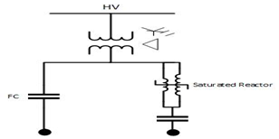
Fig. 1: Compensation with a power capacitor [17].
reactive power ![]() (1)
(1)
The voltage value obtained after solving the aforementioned equations is
![]() (2)
(2)
![]() (3)
(3)
As a result of the preceding discussion, it is obvious that injecting charging power (shunt capacitor) into the system increases the voltage profile as well as the power factor.
B. The Effect Of DG On The Line
The total power (PT) generated by a basic electrical distribution system, as shown in Fig. 2 is
PT=PG+PL ; (4)
And, energy demand PD=PT+PL (5)
and PT=PG+PDG, so we can write
PD=PG+PDG –PL(6)
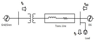
Fig.2: Basic electrical distribution with DG [17].
TEST SYSTEM DESCRIPTION
The approach is applied to a 17-node, 16-branch, and 11-static-load radial distribution system in this example. The described system has a 30920 MW active load and a 29720 MVar reactive load. PSAT software was used to simulate the circuits using a load flow methodology (NR). The system has been evaluated in two different scenarios: case 1 with FC and case II with the DG unit. The intended objectives to be achieved are as stated below:
- To calculate the network losses in the urban distribution network of Abuja Electricity Distribution Company, AEDC Minna Region.
- To assess and compare the impact of DG and capacitor banks on network voltage profiles and feeder losses.
The system under concern is the 11 kV rural feeders of Abuja Electricity Distribution Company, (AEDC) Minna, Region emanating from Shiroro 132/33 kV Transmission Station [16]. The effect of DG and shunt capacitors in the High Tension (HT) network on losses and, network voltage profile has been simulated. The Abuja Electricity Distribution Company AEDC Minna, Region feeder has been electrically modeled using Power System Analysis Toolbox (PSAT) software. A load flow study has been performed to assess the loading of 11 kV lines, feeder loss, and voltage at various feeder points. The total nodes are seventeen (17), out of which node 1 has 33 kV voltage levels, which is the swing node.
Table 1 lists the input parameters of the test system modeled in the PSAT environment.
| S/N | Input Data | Data Value |
| 1 | Total active power load | 30920 KW |
| 2 | Total reactive power load | 29720 KVar |
| 3 | Load power factor | 0.8 |
| 4 | Total of generator node (swing node) | 1 |
| 5 | Total number of nodes | 17 |
| 6 | Number of 33 kV nodes | 1 |
| 7 | Number of 11 kV nodes | 16 |
| 8 | Total number of branches | 16 |
| 9 | Number of 33/11 kV transformers | 5 |
| 10 | Total number of load nodes | 11 |
The utility is providing power supply for 8 hours considering the domestic and commercial load. There are 11 nodes for all loads, and a 0.8 power factor has been considered. Load is signified as a constant power load. The model consists of a wide variety of commercial and domestic loads. The average recorded load on a 33/11 kV power transformer is 75% of its capacity. Therefore, in the base case, at each load node, the load was connected equally to 75% of the transformer capacity with a power factor of 0.8.
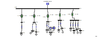
Fig. 3: PSAT Simulink model of a 17-node distribution network.
A load flow study has been carried out on the 11 kV Abuja Electricity Distribution Company, AEDC Minna Region feeder emanating from Shiroro 33/11 kV Transmission Station (TS) using PSAT software. The following two cases have been considered in the load flow study:
Case I: load flow study of existing 11 kV AEDC feeders with shunt capacitor banks.
Case II: load flow study of existing 11 kV AEDC feeders with DG. The results of the load flow study of Case-I and Case-II are plotted in Fig. 4, 5, and 6.
The effect of DG and shunt capacitor banks in the distribution network has been analyzed in the simulation studies. The DG placement has encroached on the system for stable grid operation by providing continuous power through compensation.
SIMULATION STUDY RESULTS
The designed model of the distribution network was analyzed for both cases, Case I (capacitor placement), and Case II(DG utilization). The outcomes obtained for line losses and voltage profile stability are discussed as simulation results in the following sub-sections. The effect of shunt capacitor banks and DG in the distribution network has been analyzed in the following paragraphs:
C. Effect on KW Lasses and KVAr Lasses
The active loss reduction from 1196.4 to 762.6 has been obtained by the application of the DG unit in the system, while 1005.2 was obtained by the shunt capacitor bank. The KVAr loss reduction from 603.7 to 508.1 and 387.1 has been obtained by the utilization of FCB and DG, respectively.
Table 2: Active And Reactive Line Losses of The Test Network
| Losses | Case I | Case II |
| KW | 1005.2KW | 762.6KW |
| KVar | 508.1KVAr | 387.1KVAr |
Studies indicate that distribution losses are significantly reduced with DG as compared to shunt capacitor banks on the test network.
D. Effect of voltage profile stability
The simulation studies observe a better voltage profile in case II as compared to case I. DG injects active power into the network for compensation of feeder losses, thereby stabilizing system voltage variation.
Table 3: Node Voltage for Case I And Case Ii
| Critical node volt. | Case I | Case II |
| Node 7 | 0.978pu | 0.993pu |
| Node 8 | 0.964pu | 0.979pu |
| Node 9 | 0.972pu | 1.000pu |
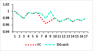
Fig. 4: System voltage with DG and FC
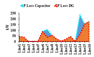
Fig. 5: Feeder energy loss at different branches.
Studies indicate that at low as well as high feeder loading conditions, at 11 kV feeders, KW and KVAr losses are less with DG as compared to shunt capacitor banks.
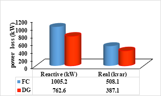
Fig.6: Real and active power loss with DG and FC
RECOMMENDATION
With the present energy crises in Nigeria, the integration of Distributed Generation (renewable energy source) technology into an existing distribution network has a paramount effect on the development of the country’s socioeconomic and technological advancement, with an attendant impact on sustainable energy and a clean environment for all. However, as observed from the result, SPVG has an effect on voltage profile improvement and power loss minimization in the distribution system, so DG is an important and essential technology that should be explored by utility and service providers to deliver reliable and quality power to consumers. Therefore, future work on DG should consider the performance analysis of the technology under different fault conditions.
CONCLUSION
Power loss reduction in any large distribution network provides considerable savings in energy and cost to the utilities. This paper advances a significant amount of simulation outcomes for the Abuja Electricity Distribution Company’s (AEDC) Minna feeder, where power is being managed to a great extent by utilizing DG and capacitor banks for comparative analysis. Considering existing conditions (voltage profile and system loading), various simulation studies are performed, and the following conclusions can be made for Case l and Case 11 (capacitor bank and DG), respectively:
- In 11 kV feeders kW, losses were reduced from 1196.4 to 762.4 with the DG-unit, resulting in energy savings of 433.8 (36.3%) as compared to the shunt capacitor bank, with losses reduced from 1196.4 to 1005.2 and energy savings of 191.2 (16.0%).
- With DG, loading on 11 kV lines has been significantly reduced. Voltage has also been increased with DG on the LV side of distribution transformers. Therefore, the quality of the power supply is also increased as compared to the shunt capacitor.
- DG in distribution feeders, the variation in node voltage is less as compared to shunt capacitors. Therefore, the voltage stability of the distribution network is improved with DG more than with the shunt capacitor.
REFERENCES
- S.E. Razavi, E. Rahimi,M.S. Javadi., A.E.Nezhad, M. Lotfi, M Shafie-khah, and J.P. Catalão. “Impact of distributed generation on protection and voltage regulation of distribution systems”.Renewable and Sustainable Energy Reviews, 105, 157-167, 2019.
- U. Sultana, A.B. Khairuddin, M.M. Aman, A.S. Mokhtar, and N. Zareen.”Review of optimum DG placement based on minimization of power losses and voltage stability enhancement of distribution system”. Renewable and Sustainable Energy Reviews, 63, 363-378.2016.
- A. M. Shaheen, E. E. Elattar, N. A. Nagem, and A. F.Nasef. “Allocation of PV Systems with Volt/Var Control Based on Automatic Voltage Regulators in Active Distribution Networks”. Sustainability, 15(21),2023:doi.org/10.3390/su152115634
- O. M. Kamel, A. Y. Abdelaziz, and A .A. Zaki Diab. “Damping Oscillation techniques for wind farm DFIG integrated into inter-connected power system. Electric Power Components and Systems, 48(14-15), 1551-1570, 2020.doi.org/10.1080/15325008.
- M. Jaramillo, and L. Tipán. “Comparative analysis of DG units against Capacitive banks in a micro-grid as an alternative for voltage profile enhancement”.IEEE International Conference on Computing, Power and Communication Technologies (GUCON) (pp. 261-267)2020.
- S.M. Ismael,S.H. Aleem,A.Y. Abdelaziz, andA. F. Zobaa.”State-of-the-art of hosting capacity in modern power systems with distributed generation”. Renewable energy, 130, 1002-1020, 2019.
- E. Karunarathne, J. Pasupuleti, J. Ekanayake, and D. Almeida, “Optimal placement and sizing of DGs in distribution networks using MLPSO algorithm”. Energies, 13(23), 6185, (pp. 1-25), 2020.
- H. Sun, Q. Guo, J. Qi, V. Ajjarapu, R. Bravo, J. Chow, and G.Yang,”Review of challenges and research opportunities for voltage control in smart grids”. IEEE Transactions on Power Systems, 34(4), 2790-2801, 2019.
- H. Gao, R. Diao, Z. Huang, Y. Zhong, Y. Mao, and W. Tang. “Parameter Identification of SVG Using Multilayer Coarse-to-Fine Grid Searching and Particle Swarm Optimization”. IEEE Access, 10, 77137-77146, 2022.
- O.A. de Koster, and J.A. Domínguez-Navarro.”Multi-objective tabu search for the location and sizing of multiple types of FACTS and DG in electrical networks”. Power System Simulation, Control and Optimization, 67, 2021.
- O. A.Coronado de Koster, and J. A. Domínguez-Navarro. “Multi-objective tabu search for the location and sizing of multiple types of FACTS and DG in electrical networks”. Energies, 13(11), 2722, 2020.
- F. Borousan, and M. A. Hamidan.”Distributed power generation planning for distribution network using chimp optimization algorithm in order to reliability improvement”. Electric Power Systems Research, 217, 109109, 2023.
- C. D. Iweh, S. Gyamfi, E. Tanyi, and E.Effah-Donyina. “Distributed generation and renewable energy integration into the grid: Prerequisites, push factors, practical options, issues and merits”. Energies, 14(17),5375,2021:doi.org/10.3390/en14175375
- M. O. Alomani, and N. A. Alqunayibit.”Minimization of Power Loss and Voltage Deviation by Using Solar Distributed Generation”. In 2022 Saudi Arabia Smart Grid (SASG) (pp. 1-6). IEEE.
- Y. Siregar, Z. Pane, and R. Sipahutar. “Optimization of Distributed Generating Power Placement And Capacity On The Distribution Network For Voltage Stability Improvement”. 5th International Conference on Electrical, Telecommunication and Computer Engineering (ELTICOM) (Vol. 5, pp. 168-173) 2021. IEEE.
- H. Mohammed, M. N. Nwohu, J. G. Ambafi and A.S. Ahmad, “Impact of Solar Photovoltaic Generation (SPVG) Distribution Networks: A case study ofMinna town 33/11kV Injection Substation”, 2022IEEE NIGERCON, pp. 471-475.
- S. Chatterjee, P. Nath, R. Biswas, and M. Das. “Advantage of DG for improving voltage profile over facts devices”. Int. J. Eng. Res. Appl, 3, 2013, pp. 2029-2032.