Comprehensive Security Framework: Integrating Intrusion Detection, Fire safety, and Environmental Monitoring in Network Infrastructure
- Amusa Afolarin
- Omeje Raphael
- Akewusola Misimi
- Adelowo Opeyemi Joshua
- 254-272
- May 9, 2024
- Computer Science
Comprehensive Security Framework: Integrating Intrusion Detection, Fire Safety, and Environmental Monitoring in Network Infrastructure
Amusa Afolarin, Omeje Raphael, Akewusola Misimi, Adelowo Opeyemi Joshua
Department of Computer Science, Babcock, University
DOI: https://doi.org/10.51584/IJRIAS.2024.904018
Received: 20 March 2024; Revised: 01 April 2024; Accepted: 05 April 2024; Published: 09 May 2024
ABSTRACT
Intrusion detection systems aim to capture security attacks & use analysers to determine details. Local wireless IDSs track all local wireless traffic and produce warnings based on signatures or abnormalities. Intrusion detection mechanisms can be configured to render unwanted access to the region easier. This paper aims to design a system to defend from intruders, human beings, through traditional surveillance devices, which cannot function in real-time, by utilising cameras fitted with infrared sensors. The aforementioned components comprise an interface program development system, intrusion detector sensors, wireless sensors, a programmable microcontroller, a controlled power supply device, Proteus relays, a GSM modem, and a cell phone. In reaction to adjustments in the atmosphere the controller activates a sensor to monitor and report input to the PIR’s wireless network. When the fire alarm device senses smoke, it can transmit a brief text message to the building’s owners. The system which uses an LM35 sensor to determine the temperature of food products, preventing fires from spreading throughout buildings without the tenants’ knowledge was produced. It is inexpensive, simple to install, and applicable to a variety of locations, including hotels, warehouses, and the automotive industry.
This research study incorporates comprehensive tactics for monitoring environmental elements and fire safety, going beyond traditional intrusion detection methodologies. In doing so, this study offers a comprehensive strategy for protecting network infrastructures against various threats. The goal of integrating these essential components is to offer a more complete and reliable security solution.
Keywords: Comprehensive Security Framework, Intrusion Detection Systems, Fire Safety Measures, Environmental Monitoring, Network Infrastructure, GSM Technology, Sensor Integration, Real-time Alerting, Arduino Microcontroller, System Design
INTRODUCTION TO INTRUSION DETECTION SYSTEM
WLANs are now widely utilized in households, businesses, and governments across the globe. According to Lindroos et al. (2021), they still provide a security concern, though, because files can be accessed without authentication or encryption. WIDS, or wireless intrusion monitoring systems, can reduce these risks by putting in place security measures to stop unauthorized access. Ismail et al. (2019) further stated that currently in use in a number of nations, GSM technology gathers signals from nearby equipment and sends control signals to distant machines.
The exponential growth of network and internet technology has led to an increase in network infiltration, making it more challenging to defend against malevolent hackers as stated by Ibrahim (2022). Hence, devices for preventing intrusions are used to monitor networks and keep intruders out. Tripathi et al. (2023) further stated that the adoption of interactive and wireless technologies, such GSM and SMS, has led to advances in home security by identifying visitors and keeping an eye on device settings, intelligent home monitoring systems, which can include managed networks and communication systems, offer additional security.
Although home monitoring systems have long been a feature of science fiction, they are nevertheless frequently employed in real life because of IT improvements. With the introduction of electrical home appliances between 1915 and 1920, remote control systems first appeared in the late 1800s as explained by Corn and Heflin (2022); Maloberti and Davies (2022). Due to the fact that home automation is inexpensive and easy to use with smartphones, phones, and cable systems, it has thus become more popular.
Connecting home monitoring devices to other technological systems might convey advantages related to safety, energy efficiency, and comfort according to Sovacool and Del Rio (2020). Utilizing computer and information technology, home automation entails keeping an eye on systems and features within the house, like lighting controls, doors, and windows. The three main goals of home monitoring systems are energy conservation, security, and convenience. One such use case for home automation is smoke detectors, which can recognize a probable fire, alert the home monitoring system, and get in touch with the homeowner or neighbor.
Hence, this paper aims to look into the design of a system which can detect and prevent intrusion, thereby ensuring the security of homes and environments.
In light of evolving security challenges, this article aims to broaden the ambit of conventional intrusion detection systems by advocating for a holistic security strategy. It proposes an integrated architectural framework that not only encompasses the detection of unauthorized entry but also encompasses the monitoring of environmental anomalies and fire hazards. By establishing a multi-tiered defensive mechanism, this comprehensive approach bolster network infrastructure security and resilience against a diverse range of threats.
Technologies Used
The components utilized in the system design are as follows:
Sensor
- PIR sensors give an electric signal to show a difference in thermal radiation. The release of radiation rises as the body temperature increases. Industrial PIR sensors typically contain two IR sensitive components with opposite polarizations installed in a hermetically sealed metal shell (typically coated silicon to protect the sensing element). An item will move by the two pieces of the sensor, and the ones with a favorable difference on the opposite sides will turn on. The sensor induces a negative differential shift when the warm body exits the sensing field. These signs are observed.
- Integrated home surveillance device piezoelectric module used as a vibration sensor. A piezoelectric sensor uses the piezoelectric effect to calculate friction, acceleration, strain or force.
- Smoke sensor: Shah et al. (2019) stated that a fire alarm is a system that senses smoke, such as an indication of fire. Commercial, and mass residential systems normally utilize a fire alarm system. In contrast, household alarms typically transmit a local auditory or visual alarm to the occupant.
PIR Sensor on Arduino Computing – motion tracking using PIR sensor on Arduino IDE: The source code is inserted into Arduino by linking the Arduino with a device using a USB cable.
We want to track home with 3 separate sensors.
- Vibration: breaking into the building.
- Fire sensor: sparks or fire.
- PIR sensor
The machine includes an information processing module, single-chip microcomputer control module, and warning module. The shift in temperature and smoke concentration can occur when a fire occurs. Sensors can sense minor shifts. They can alter the ordinary natural state and produce an analogue signal. After encoding, the signal would be sent through the single-chip microcomputer.
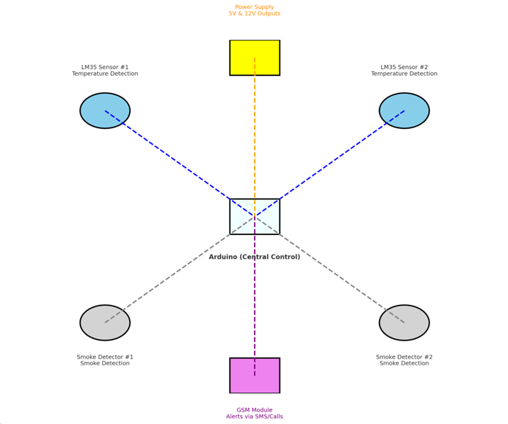
Suppose there is a signal being sensed from the single-chip microcomputer. In that case, the device can give an AT order to the global mobile communication module. The machine sends out the fire details in quick texts to the cell phone of the appropriate staff to warn them. Diagram of the device in Figure 3.1.
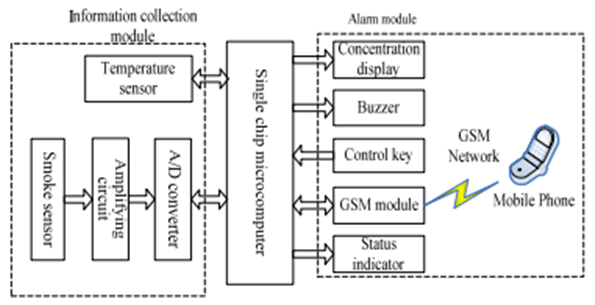
Figure 3.1: Block diagram of the system
Power Supply Module
1) Transformer is a key part of the power supply module. Transformer forms are either Phase up or Step down. 5 volts and 12 volts DC need to be produced from the 230 volts input AC source. 15 volts output / 500 mA is also needed on the current transformers.
2) To remove the positive signal from the output signal, a capacitor is required. There are three different kinds of rectifiers: bridge, half-wave, and full-wave. Since a bridge rectifier provides more efficiency, it was utilized. At its output, a rectifier converts the input’s polarity, either positive or negative. An entirely positive (negative) voltage/current waveform is produced by coupling the positive (negative) and inverted negative (positive) sections of the input. A single-phase AC is center-tapped, and a full wave rectifier is created by stacking two diodes one behind the other. A full-wave bridge rectifier with a 50-ampere surge level is made using a 1N4007 diode.
3) A capacitor is needed to eliminate the AC signal from the performance of the rectifier. A filter capacitor eliminates ripples from a pulsating DC and transforms it into unregulated DC. A capacitor stores energy in an electric field between two closely separated conductors. As voltage is added to the capacitor, positive electric charges build up on the layer. According to Yadlapalli et al. (2022), capacitors are used as energy storage machines. They can distinguish between high and low-frequency signals and be used in filters. Sidik et al (2020) also reported that these minor errors in our electric appliances will become harmful when running at high currents or temperatures above average.
Two distinct voltage regulators provide a constant 5 volt and 12 volt supply after the filter capacitor. The voltage regulators 7805 and 7812 were employed. These are input, ground, and output three-pin integrated circuits. We receive 5 and 12 volts at the regulator’s output after sending the output to the regulator’s input. Output current larger than 1 A and no extra components needed.
Output transistor safe-area compensation voltage given in 2% and 4% tolerance.
Fabrication of Power Supply Unit Materials
- 12 V Transformer
- NPN diodes
- 620 µF/25 V capacitors
- 5 V regulator
A simple phase is the first step in designing a device’s power supply. A 12V phase down converter, a bridge rectifier, a 620μF capacitor, and 7805 controllers make up the power supply unit. If you add the 240 V D.C. Control to the converter, it will change the voltage to D.C. The capacitor sets off the injection of D.C. The LM7805 controls the voltage to give a 5V DC voltage. Changing the voltages has an effect on the circuit’s output. Moving the input voltage down to 12 V by the transformer is what makes the bridge rectifier work.
The circuit is made up of four diodes that work in a full-wave bridge rectifier mode. It gives a steady d.c. voltage of 5 V ± 0.1% in this setup, thanks to the regulator. The capacitor lowers the voltage at the input or exit of the supply and filters it. In order to change 12 Vac to 12 Vdc, we need a converter. Pulsating DC is made by the rectifier and is used in a full waveform generator.
There are four diodes in it. An AC sine wave is changed into a full-wave pulsing DC signal by full-wave bridge rectifiers. A usually linked secondary is built into the transformer. The present moves from a promise that is higher to one that is lower. During the positive half-loop, diode D1 will not carry current, but diode D2 will. The current will flow through diode D3, but not through diode D4. During the negative half cycle, D1 will be forward biased and flow current. In this case, D2 will have a backward bias and no conducted current. D3 is biased backwards, but D4 is slanted forward and can carry current. Pulsating DC is how the rectifier works. DC that pulses can be turned into straight DC with a transformer. It is possible to filter with a capacitor. How well a capacitor works is based on the current and energy. Here’s how to figure out the value of a capacitor.
Q=C V
But V = IR
‘Also’,
‘Q=I T’
‘Substitute equation (3) in equation (1)’,
‘I T=C V’
‘C= (I T)/V’
‘Here, the output voltage is V=5DC’
‘Output current is I =300Ma’
‘The input voltage is AC 240V, 50 Hz. The output of the transformer is 12VAC, 50 Hz’
‘So, f=50 Hz, (for ac)’
‘F=2 50Hz=100 Hz (for dc)’
‘T=1/f’
‘=1/100 Hz’
‘T=0.01s’
‘Therefore’
‘C= (3 10-3 0.01)/5’
‘C=0.0006F’
‘C=600 F’
The capacitor had a 600 µF value. 620 µF was utilized in order to bring the capacitor’s value to match that of 600 µF. To control the voltage regulator down to its designated voltage, a smooth DC signal must be delivered into it. The regulator’s output voltage must be lower than the input voltage. The appropriate voltage for the electrical input needs to be at least 2 volts higher. Seven volts will fit perfect. The centre pin is grounded. If the circuit has no field, it would not be full, so there would be no voltage and return path. Pin 3 is the output pin.
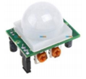
Figure 3.2. 5V power supply
PIR Sensor
An Infra-Red sensor (PIR) senses thermal radiation emitted by human bodies according to Kazi and Parasar (2021). Infrared devices detect radiation levels. Ultrasound detection systems are lightweight, affordable, easy to use, and sturdy. The colder the body, the stronger the radiation. Yun and Woo (2019) defines a PIR sensor as that which detects the motion of animals, people, or other objects. This sensor will be used to track outside activity. A sensor can sense a particular person approaching the border and alert the control room. A computer based on the Internet of Things that can track space was also implemented.
GSM: – A GSM, according to Prochazka et al. (2020), is a wireless modem that works with a GSM network. A dial-up modem is a cellular modem. The cellular modem uses a radio signal to transmit and receive data. The dial-up modem, on the other hand, uses a fixed connection to send and receive data. Devices that use GSM mobile SMS services can be managed by a SIM card from a network using a GSM mobile system.
The microcontroller wants to submit “AT” to the modem. Return “OK” whether a cell phone is used. Reading messages from the SIM card inserted into the modem is accomplished with the AT button.
Interfacing the GSM Modem with Microcontroller
The modem can be directly attached to a 5V microcontroller including PIC, AVR, 8051, ARDUINO, ARM, ARM Cortex XX etc. Make sure V INTERFACE receives the same voltage as the microcontroller VCC. As seen, there are only 2 connections required to use the modem. The modem was linked to the microcontroller and the microcontroller to the modem. The attached power supply should accommodate current up to 1 A.
Fire Sensing Device
The key sensing system used in this study is addressed in depth. They have named platinum resistance thermometers (PRTs). They are replacing the use of thermocouples for several that regulates resistance thermometry.
Rt = R0 (1+)
Where Ro=resistance at reference
Temperature (usually ice point,00 c)
Rt = resistance at temperature t,
=temperature coefficient of resistance, (0C)
=coefficient calculated based on two or more know resistance temperature (calibration) points
The resistance of the RTD declines as temperature rises and increases as temperature decreases. RTDs respond to changes in temperature by translating voltage to a calculated resistance. The metals used for RTD sensors are pure, consistent in quality, range over a specified temperature.
Connecting the Modem to the Arduino
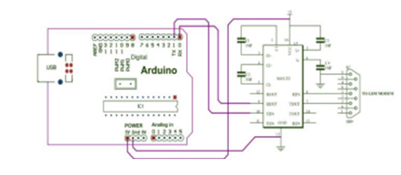
Figure 3.3: connection of GSM Modem to Arduino
Getting started:-
- Insert SIM card: Click the arrows and then raise the tab to open the key. Place the SIM card in the SIM card holder, and then match the chamfered corner on the cardholder to the opposite side of the arrow symbol.
- Connect the Antenna: Tighten the included RF antenna by connecting it to the SMA connector; never spin the antenna while tightening it.
- Join the Pins: Attach the schematically specified modem.
- Turn on the Modem: To generate enough current, turn on the modem using a power source.
- Verify the LEDs’ status: PWR LED: When turned on, red LEDs will illuminate; a few seconds later, the NET LED will also light up (Searching for Network). Network LED: The GSM Network Lead shows various standing. Connecting to the Wi-Fi and network.
- Baud rate: The modem’s Baud rate is between 9600 and 115200. Verify that the host system’s baud rate is supported. The modem is set to a particular baud rate until it is turned on. To sync the baud rate, “A” must be received. Wait for 2 to 3 seconds before submitting the ‘AT’ character. Once the process is OK, the instruments are properly coordinated. Setting the baud rate is not required through commands.
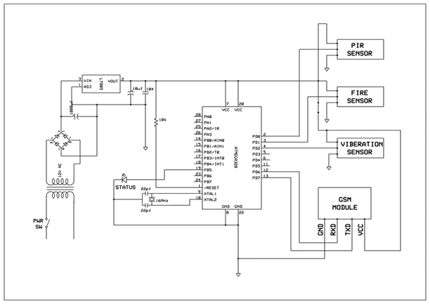
Figure 3.4: Circuit Diagram.
Figure 3.4 shows the complete circuit diagram for the intrusion detection system. If someone is not at home, the three sensors will be active. We incorporate a GSM module and Amigas 328 microcontroller is used. Each will be running, and if any of the sensors senses, it will send to the microcontroller. The GSM module is activated to send messages to a particular number already embedded inside the microcontroller.
Fire Safety Measures
Introduction to Fire Safety
The incorporation of fire safety measures into security systems signifies a substantial advancement in the protection of network infrastructures and physical assets. Fire, a persistent hazard, possesses the capability to cause significant damage to both property and human lives. The integration of fire safety technologies not only aids in the early detection and prevention of fire incidents but also ensures the uninterrupted continuation of operations and provides safeguards against potential data loss. The convergence of fire safety with established security measures enables a comprehensive response strategy, thereby enhancing the overall safety and resilience of the system against multifaceted threats.
Technologies Employed in the Fire Safety System
In the realm of fire safety, the utilization of specific technologies plays a pivotal role in ensuring the reliability and precision of early fire detection. Among these technologies, the LM35 temperature sensor and smoke detectors stand out for their exceptional performance. The LM35 sensor, renowned for its accuracy across a broad temperature range, serves as an instrumental tool in detecting unusual heat levels that may indicate the onset of a fire. Complementing this capability, smoke detectors provide a secondary layer of protection by identifying the presence of smoke, often the initial indicator of a fire, thereby facilitating prompt response efforts before the situation escalates.
The integration of these sensors into the comprehensive security system is achieved seamlessly, enabling continuous monitoring of sensor data for any signs of fire. Upon the detection of abnormal temperature or smoke levels, the system is configured to trigger alarms and initiate a standardized alert protocol, ensuring a timely and effective response.
Alerting Mechanism
Integral to the fire safety system is the notification mechanism facilitated by GSM technology. This technological advancement ensures that building owners, occupants, or designated security personnel are expeditiously apprised of fire incidents, irrespective of their geographical location. Through the transmission of SMS or automated phone calls, the system promptly disseminates information, permitting immediate action to minimize the consequences of the fire.
System Design
The design of the fire safety system prioritizes the maximization of early detection and the facilitation of a prompt response. Calibration of the LM35 temperature sensors and smoke detectors is meticulously conducted to optimize sensitivity and minimize the occurrence of false alarms. Criteria for triggering alerts are established based on a combination of factors, including the rate of temperature increase and the density of detected smoke, ensuring the relevance and actionable nature of alerts.
Programming and configurations pertaining to fire detection and alerting are customized to align with the specific requirements of the infrastructure being protected. This may involve the establishment of threshold levels for temperature and smoke, which, when surpassed, activate the GSM alerting mechanism. Schematics and code snippets provided within the system design offer insights into the technical foundation of the fire safety measures, demonstrating their integration with the broader security framework.
Through this integrated approach, the fire safety measures contribute not only to the physical security of the infrastructure but also enhance the overall safety and well-being of the occupants, representing a significant advancement in the development of comprehensive security systems.
Environmental Monitoring for Safety
Introduction to Environmental Monitoring
In the realm of comprehensive security, environmental monitoring emerges as a vital facet, transcending the conventional scope of intrusion and fire detection. The rationale for its integration lies in the multitude of environmental factors that could pose risks to safety and well-being. Gas leaks, significant temperature fluctuations, toxic fume emissions, and abnormal humidity levels are all examples of environmental anomalies that, if undetected, could lead to catastrophic events. Monitoring these parameters not only ensures the safety and structural integrity of facilities but also contributes to the health and comfort of occupants, thus complementing the overarching security infrastructure.
Proposed Technologies and Integration
To mitigate the multifaceted risks posed by the environment, a diverse array of sensors can be strategically deployed, each meticulously calibrated to detect specific anomalies with utmost precision.
Examples include:
- Carbon Dioxide (CO2) Sensors: These indispensable devices are essential in environments where air quality is of paramount importance. They assiduously monitor carbon dioxide levels and promptly trigger ventilation systems when predetermined thresholds are exceeded, ensuring that air quality is maintained at a salubrious standard.
- Humidity Sensors: By meticulously measuring the moisture content present in the air, these sensors proactively prevent the growth of mold and preserve structural integrity, particularly in locales prone to dampness or in sensitive environments such as archives or server rooms, where humidity control is crucial.
- Volatile Organic Compounds (VOC) Detectors: These sensors vigilantly identify the presence of potentially harmful chemicals in the air, which could serve as an early warning indicator of toxic fumes emitted from spills or industrial processes, enabling timely intervention and safeguarding the health and well-being of individuals.
- Thermal Cameras: While renowned for their fire detection capabilities, thermal cameras also possess the remarkable ability to detect overheating equipment, thereby preventing machinery failures and averting industrial accidents, ensuring the smooth and efficient operation of critical infrastructure.
The effective integration of environmental sensors in the pre-existing security framework can be achieved through the implementation of a centralized management system, which would be ideally controlled by a microcontroller or a computer system capable of processing complex datasets. This system would act as a pivotal hub, collecting data from a diverse array of environmental sensors. By utilizing advanced algorithms and defining predefined thresholds, the system could efficiently identify potential hazards and initiate appropriate automated responses or alerts. For instance, in the event of detecting elevated carbon dioxide (CO2) levels, the system would automatically activate air purifiers or initiate the opening of ventilation shafts. Moreover, it could seamlessly interface with the GSM module to promptly alert maintenance personnel of any detected anomalies.
Furthermore, the networking of these environmental sensors with the existing intrusion detection and fire safety systems would facilitate the creation of a comprehensive monitoring platform. This integration would enable a holistic approach to security, wherein environmental safety is accorded the same level of priority as the prevention of unauthorized access or fire outbreaks. In light of the growing significance of the Internet of Things (IoT) in smart building management, the proposed system could leverage IoT protocols and platforms to enhance connectivity, real-time monitoring capabilities, and remote management functionalities, thereby optimizing the overall security and efficiency of the building.
Fire Temperature Sensor Analysis
The LM35 sensor is employed. With every degree Celsius that the temperature rises, the voltage output of the LM35 increases by 10 mV. A 5 V power supply can run the LM35, and its standby current is less than 60 µA. The link between temperature and LM35 output is determined to enable temperature measurement with a microcontroller. The relationship provides LM35’s transfer function: Vout is equivalent to 10 mV/oC times temperature because the device is designed to react at 40 oC. As a result, the device’s transfer function will be Vout = 0.01 × 40 = 0.4V. The output temperature rises by 0.01 V for every degree that the temperature rises. Table 1 displays the output voltage for a selection of temperature levels.
Table 1: Relationship between temperature and output voltage of LM35
| S/N | Temprature(0C) | Output voltage(V) |
| 1 | 0 | 0 |
| 2 | 1 | 0.1 |
| 3 | 2 | 0.02 |
| 4 | 20 | 0.2 |
| 5 | 40 | 0.4 |
| 6 | 60 | 0.6 |
| 7 | 80 | 0.8 |
| 8 | 100 | 1 |
| 9 | 120 | 1.2 |
| 10 | 140 | 1.4 |
The sensor has a temperature perception range of -55oC to 150oC with an identical relationship. To obtain the temperature from the output voltage, the value must be multiplied by 100.
The complete schematic diagram is shown in Figure 8. The schematic diagram of the connection between the Arduino UNO board with LM35 and the GSM module is shown in Figure 9. Since the GSM module component is not included in the Proteus© program, it is substituted with the available input connector. The connection pins will be soldered straight to the Arduino UNO board. The code for the particular piece that deals with detecting fire from LM35 is created and displayed in figure 4.3. The temperature that the code has detected from the surroundings is indicated by the voltage. This is because the LM35 is an analog sensor that values voltage in units of magnitude. The received voltage unit will then be converted by the ‘CheckTemp()’ method into a unit that is easily recognized in standard SI: degree Celsius.
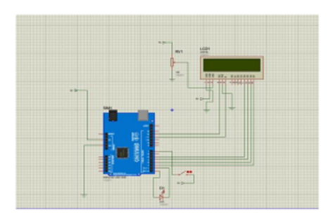
Figure 4.1. Project schematic diagram.
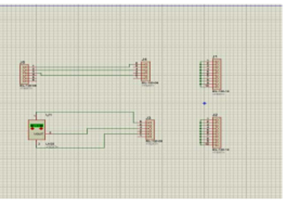
Figure 4.2. The schematic diagram for connection between Arduino UNO board with GSM module and LM35.
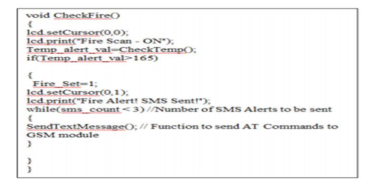
Figure 4.3. The program code for measuring temperature.
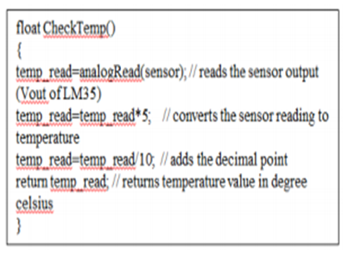
Figure 4.4. The program code for checking temperature and converting it to degree Celcius.
Proteus Simulation
Step 1: Elements Power supply for GSM MODULE 10k Potential Meter for Arduino Uno LCD 16X2 LM35 TEMP SENSOR GSM MODULE 5V Power supply for Arduino 12V
Step 2: Download the file to launch the Proteus demo. Operate in the Proteus Virtual Terminal as a GSM Module You can adjust the temperature to your preferred setting, but bear in mind that 25 degrees is about average for a room temperature. Make sure your room temperature is known before setting your temperature threshold, and then base the threshold value on that temperature. If (Temp_alert_val>45), then we set the temperature threshold value in the code. An SMS informing the user of a fire will be sent to their mobile number when the temperature hits 45 degrees. You can enter a person’s phone number in place of this mobile number to receive a fire alert SMS (“AT+CMGS=\”+2348032343270\”\r”).
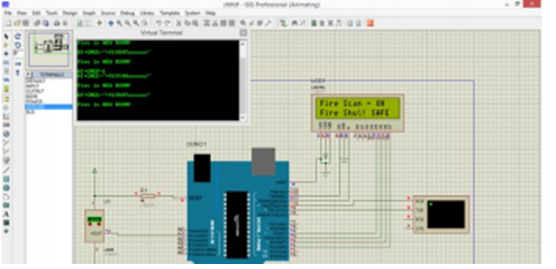
Figure 4.5a: Proteus simulation
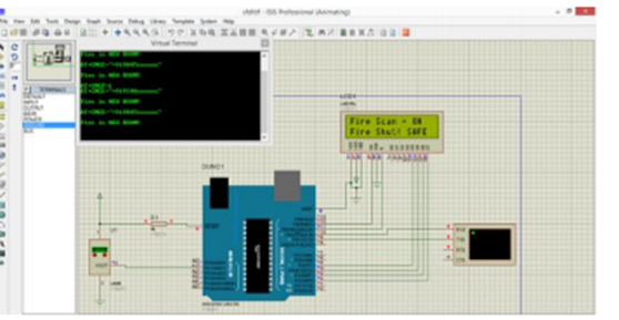
Figure 4.6b: Simulation
PIR Sensor Output
When the intruder window sensor (shown by the response from the gates output in Figure 4.8) or the intruder door sensor is activated, the display’s output is shown in Figures 4.7a and 4.7b, respectively. Figure 4.7d shows the output of the display when a smoke detector (Figure 4.7d) or gas leakage sensor (Figure 4.7c) is triggered. At this point, the security module and central sensor-connected continuous alarm circuit is also turned on. Until the user resets it, it stays in the active state, signifying that the message was sent successfully. Figure 4.8 shows two output waveforms.
Table 2. Maximum Power consumption of the GSM serial wireless module
| ‘Model’ | ‘Voltage (V)’ | ‘Current (mA) max’ |
| Sending | 3.3 | ‘120mA’ |
| Receiving | 3.3 | ‘45mA’ |
| Standby | 3.3 | 40mA |
The mean power consumption of the sensor network module and the central sensor and security system, as determined by Tables 3 and 4, is presented. The power consumption is captured during standby, transmitting, and receiving operations, with the devices positioned at an approximate distance of 20 meters apart.
Table 3. Average measured total power consumption of the Sensor network module
| ‘Mode’ | ‘Voltage (V)’ | ‘Current (mA) max’ |
| ‘Sending’ | 12 | ‘49.67mA’ |
| ‘Receiving’ | 12 | ‘29.04mA’ |
| ‘Standby’ | 12 | ‘27.67mA’ |
It is significant to remember that the average power consumption listed above accounts for the power consumed by every circuit component in both modules. The power supply requirements for each module can be rapidly estimated using the mean values displayed in Tables 5 and 6. The average current consumed by the sensor network module to transmit data to the central sensor and security module at 12V (49.67 mA) is shown in Table 5. This aids in figuring out the power rating required by the power source to operate this module.
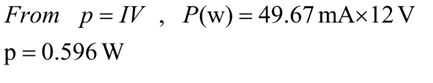
For optimal performance, the sensor network module needs an average power supply of roughly 0.6 Watts. This power requirement can be satisfied with a solar rechargeable battery. Furthermore, as Table 4 demonstrates, when transmitting data to any of the sensor network modules, the central sensor and security module uses its maximum current of 116,3 mA at 12V. This facilitates the process of estimating the power rating of the power supply unit’s component elements.
![]()
Table 4 Average measured the total power consumption of the Central sensor and security module.
| Mode | Model voltage (V) | Current (mA) |
| Sending | 12 | 116.3mA |
| Receiving | 12 | 95.7mA |
| Standby | 12 | 94.33mA |
To function at maximum efficiency, the primary wireless sensor and security system module necessitates a power supply device with a wattage of 1.4. Considering the aforementioned points—such as the improbability of fire or smoke detector activation for weeks or months—and the average power consumption of the modules, in addition to the information presented in Tables 3 and 4, it can be inferred that this system maintains a perpetual standby state. On the basis of this assumption, a detailed description of the module’s power consumption follows. Energy consumption of wireless sensor modules and the security system At the core, there are three distinct power consumption scenarios: 1.15W is allocated for data reception, 1.13W is reserved for inactive time, and 1.4W is utilized for data transmission. 0.6W of power is consumed during data transmission, 0.35W during data reception, and 0.33W during inactive time by the sensor network module. The dependability of the sensor network module design is computed using Table 7.
In spite of the fact that the Central Wireless Network module is dependable,
From
In the worst-case situation, the reliability result is dependent on the Central wireless module and Sensors network module functioning constantly for the entire year. Interestingly, in both configurations, over 68% of the overall failure rate can be attributed to the capacitors and resistors that are part of the system design. Thus, high ratings lead to a significant improvement in reliability. To further avoid damage, make sure the connectors are routed correctly on the PCB. As a result, the system’s reliability can reach 97.5% or higher. Simultaneously, the small design, which only affixes a few components to the modules to guarantee correct operation, increases the stability of the system. The system response’s computed total harmonic distortion (THD) is 2.37%. However, using a distortion analyzer, the reported THD at 500 m between the sensor network module and the central wireless security system ranges from 1.29% to 3.63%. The real noise levels were 2.34dB and 1.52dB, while the computed signal noise was 1.79dB. About 72% of the maximum derivable for system propagation, or -42.7dBm, is reached by the signal strength. The system is projected to be 96.7% efficient and easy to maintain with a small number of components.
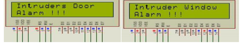
Figure. 4.7a and Figure 4.7b Output from the display when at least one switch in the PIR sensor group is activated
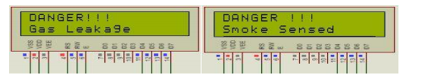
Consider Figures 4.7c and 4.7d. If at least one switch in the smoke detection sensor group is activated, the corresponding value will be displayed.
Table 5. The failure rate of Basic circuit components for Sensor network module design
| Components Number used Basic failure rate, Weighing factors due to Overall failure. | ||||||
| γ (%/103 hr) ____________________________ rate, γoi=niγi | ||||||
| Envr.WE | Temp.WT | Rating. WR | WE WT WR | |||
| Transistors | 02 | 0.008 | 2.0 | 1.5 | 2.0 | 0.096 |
| Diodes | 07 | 0.005 | 2.0 | 1.5 | 1.5 | 0.158 |
| Capacitors | 10 | 0.01 | 2.0 | 1.5 | 3.0 | 0.9 |
| Resistors | 12 | 0.005 | 2.0 | 1.5 | 2.0 | 0.360 |
| Connectors | 100 | 0.001 | 2.0 | 1.5 | – | 0.3 |
| Switches | 02 | 0.001 | – | – | – | 0.002 |
| IC’s | 06 | 0.002 | – | – | – | 0.012 |
| Sensors | 06 | 0.001 | – | – | – | 0.006 |
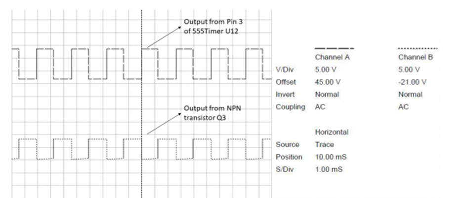
Figure 4.8. The output waveform from the alarm circuit
Table 6. The rate of failure of fundamental circuit elements utilized in the design of a central wireless network module
| Components Number used Basic failure rate, weighing factors due to Overall failure. | ||||||
| γ (%/103 hr) ____________________________ rate, γoi=niγi | ||||||
| Envr.WE | Temp.WT | Rating. WR | WE WT WR | |||
| Transistors | 02 | 0.008 | 2.0 | 1.5 | 2.0 | 0.096 |
| Diodes | 07 | 0.005 | 2.0 | 1.5 | 1.5 | 0.158 |
| Capacitors | 10 | 0.01 | 2.0 | 1.5 | 3.0 | 0.9 |
| Resistors | 12 | 0.005 | 2.0 | 1.5 | 2.0 | 0.360 |
| Connectors | 100 | 0.001 | 2.0 | 1.5 | – | 0.3 |
| Switches | 02 | 0.001 | – | – | – | 0.002 |
| IC’s | 06 | 0.002 | – | – | – | 0.012 |
| Sensors | 06 | 0.001 | – | – | – | 0.006 |
RESULTS AND DISCUSSION
Within the context of this discourse, the discussions extend beyond the mere detection of intrusions, encompassing a comprehensive framework of strategies aimed at mitigating fire risks and other environmental hazards. This integrated approach facilitates the establishment of a multifaceted defensive mechanism capable of addressing diverse threats. It leverages the interconnectedness of intrusion detection, fire safety protocols, and environmental monitoring, thereby enhancing overall security and resilience.
Limited attempts were made to evaluate the efficacy of the system. To conclude the experiments, heat was applied in close proximity to the LM35. The state depicted in Figure 4.9 illustrates the LM35 in readiness mode, where it is prepared to detect fire but fails to do so. An alert message is displayed on the LCD when the LM35 detects fire, as shown in Figure 4.10. However, figure 4.11 illustrates the state of affairs once the fire has been extinguished. The SMS that the user receives in response to a fire alert from the system is depicted in Figure 4.12.
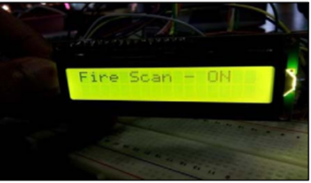
Figure 4.9. When the fire is still not detected, LM35 is in ready mode.
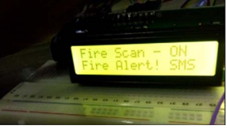
Figure 4.10. When the fire is detected.
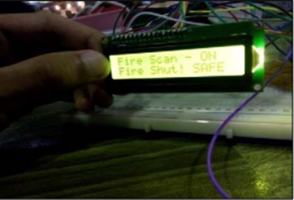
Figure 4.11. When the fire has been put out.

Figure 4.12. SMS received by the user to notify the fire’s existence.
Table 1 provides an analysis of the output temperature during the course of the test measurements. The LCD exclusively displays the LM35 sensor’s preparedness to identify the fire when it is detected. Upon LM35 detecting a fire, the LCD screen will flash “Fire alert!” in time with the SMS sent to the user by the GSM module, which also notifies the user of the fire’s presence. Once a fire has been extinguished, the LCD will display the message “Fire extinguished!” “Safe now” appears on-screen.
Table 7. Examination of the temperature output of LCD and GSM modules.
| Components | |||
| Involved | Before fire detection | during fire detection | After fire detection |
| LCD Display | Fire scan-on | Fire alert | Fire shut Safe now |
| GSM | Fire in HOUSE | ||
Owners of buildings can use the device to contain flames even when they are not present. Unexpected events or dangerous conditions arise in buildings without informing inhabitants. Based on the results, the gadget can be implemented and is helpful in securing the rooms. In actuality, the gadget is easy to install and performs at a lower cost than other alarm systems on the market. This device calculates the high temperature of food goods using an LM35 sensor. The system’s robustness and ease of use allow it to be used in a variety of contexts. It can be applied, for example, in automobile companies, hotels, and warehouses. In the areas where you wish to protect yourself from fire, apply the technique. The user will immediately receive an SMS message from the system when it reaches its cap. Customers may be alerted to the dangerous situation and take prompt action to avoid it (using fire extinguishers, calling firefighters, etc.).
CONCLUSION
The study findings and technology breakthroughs reported in this academic piece highlight the crucial need for a complete security framework that includes not only intrusion detection but also effective fire safety and environmental monitoring systems. The adoption of a comprehensive strategy like this boosts network environments’ security effectiveness considerably and offers a diversified defence against various threats.
Protection of the country is a big concern. Nevertheless, at the same time, the lives of border guards must be secured. Arms do not operate through the workforce only; they need smart weapons. The innovation of technology helps provide defence without posing risks to the soldiers. The principles addressed to protect the border successfully and reduce life risks. The company assumes that approved workers can use their employee id card during working hours to reach the data centre, while, during off-office hours, the motion sensors will be switched on. Suppose the company aims to add motion sensors. In that case, it often includes how the reaction time can be increased when the motion sensor senses and informs about the intrusion. Giving the power to monitor the sensors to more than one individual will be a security violation. To prevent the pitfalls and risks of manually monitoring the motion sensors, the organisation opted to monitor them remotely using GPRS. A specified approved staff may switch ON/OFF the sensors conveniently from any location, wirelessly, via GPRS. This automatically allows it to manually protect the protection aspects relevant to interacting and controlling with the motion sensors. Intrusion identification and measurement was important aspect of physical security schemes. Detection and evaluation establish a framework for beginning a protection response. An IDS can enable identifying illegal entry attempts and offer notice of the intrusion occurrence to the owner’s smart device. The methods of identification and evaluation chose should be robust and have the maximum standard of security for the particular application.
RECOMMENDATIONS
- Given the investigations and conclusion, it could be best to develop smoke detector systems. Security procedures can still be done to inspect and ensure the machinery is operated against unnecessary warnings and equipment failure.
- Testing and inspections are necessary and can be carried out by a trained specialist on a routine set out in a standardised fire risk evaluation. Fire detectors can be tested and serviced every two or four years.
- Research efforts should continue to explore and improve the effectiveness of these all-encompassing security systems in the future, focusing especially on improving the reliability, effectiveness, and scalability of the system’s constituent parts. Furthermore, it is advised that future research examine the integration of new technologies such as AI and IoT to improve the predictive capabilities and overall responsiveness of the systems in issue.
LIMITATIONS FOR FUTURE RESEARCH
A low cost, safe, widely available, remotely operated computer has been launched. The strategy, which includes monitoring appliances remotely by triggering notifications by alerts, is novel and achieved. A future device would have a small box incorporating the PC and GSM modem and GCM functionality.
REFERENCES
- Lindroos, S., Hakkala, A., & Virtanen, S. (2021). A systematic methodology for continuous WLAN abundance and security analysis. Computer Networks, 197, 108359.
- Ismail, G., Mubdir, B. A., Majeed, A., & Al-Hindawi, A. M. J. (2019). Monitoring and Controlling Electric Power Stations Using GSM Network. Kurdistan Journal of Applied Research, 4(2), 80-89.
- Ibrahim, H. (2022). A Review on the Mechanism Mitigating and Eliminating Internet Crimes using Modern Technologies: Mitigating Internet crimes using modern technologies. Wasit Journal of Computer and Mathematics Science, 1(3), 50-68.
- R., Tripathi., Harjinder, Singh., Ajay, Chakravarty. (2023). Smart home sensorized security system. Nucleation and Atmospheric Aerosols, doi: 10.1063/5.0125061
- Corn, M., & Heflin, K. (2022). Remote control: a cultural history. Media History, 28(2), 244-260.
- Maloberti, F., & Davies, A. C. (Eds.). (2022). A short history of circuits and systems. CRC Press.
- Sovacool, B. K., & Del Rio, D. D. F. (2020). Smart home technologies in Europe: A critical review of concepts, benefits, risks and policies. Renewable and sustainable energy reviews, 120, 109663.
- Shah, R., Satam, P., Sayyed, M. A., & Salvi, P. (2019). Wireless smoke detector and fire alarm system. International Research Journal of Engineering and Technology (IRJET), 6(1), 1407-1412.
- Kazi, N., & Parasar, D. (2021, May). Human Identification Using Thermal Sensing Inside Mines. In 2021 5th International Conference on Intelligent Computing and Control Systems (ICICCS) (pp. 608-615). IEEE.
- Yun, J., & Woo, J. (2019). A comparative analysis of deep learning and machine learning on detecting movement directions using PIR sensors. IEEE Internet of Things Journal, 7(4), 2855-2868.
- Procházka, V., Kubalík, P., & Kubátová, H. (2020, June). Low power wireless data transfer for Internet of Things: GSM network measuring results. In 2020 9th Mediterranean Conference on Embedded Computing (MECO) (pp. 1-5). IEEE.
- Procházka, V., Kubalík, P., & Kubátová, H. (2020, June). Low power wireless data transfer for Internet of Things: GSM network measuring results. In 2020 9th Mediterranean Conference on Embedded Computing (MECO) (pp. 1-5). IEEE.
- Yadlapalli, R. T., Alla, R. R., Kandipati, R., & Kotapati, A. (2022). Super capacitors for energy storage: Progress, applications and challenges. Journal of Energy Storage, 49, 104194.
- Sidik, A. D. W. M., Kusumah, I. H., Suryana, A., Artiyasa, M., & Junfithrana, A. P. (2020). Design and Implementation of an IoT-Based Electric Motor Vibration and Temperature Disruption Handling System. FIDELITY: Jurnal Teknik Elektro, 2(2), 30-33.