IOT-Enabled Radio Frequency Home Automation System
- Amusa Afolarin
- Akewusola Misimioluwa
- Omeje Raphael
- Mensah Yaw
- Bamidele Oluwadoyin
- Adelowo Opeyemi
- 425-437
- May 24, 2024
- Computer Science
IOT-Enabled Radio Frequency Home Automation System
Amusa Afolarin, Akewusola Misimioluwa, Omeje Raphael, Mensah Yaw, Bamidele Oluwadoyin, Adelowo Opeyemi.
Department of Computer Science, Babcock University
DOI: https://doi.org/10.51584/IJRIAS.2024.904031
Received: 29 March 2024; Revised: 19 April 2024; Accepted: 23 April 2024; Published: 24 May 2024
ABSTRACT
The number one objective of this undertaking is to expand a present-day home automation device that leverages the abilities of the Internet of Things (IoT) and Radio Frequency (RF) technology. This device aims to deal with the evolving wishes of cutting-edge households through transitioning from manual switches to centralized, far flung-controlled systems. By integrating IoT-enabled gadgets which include smartphones, laptops, and drugs, the gadget gives improved comfort and manipulation over a extensive range, contingent upon the supply of a stable internet connection. Furthermore, this machine isn’t always most effectively beneficial for residential use but also affords sizable ability for business applications in business and medical settings. The integration of RF technology affords a simplified and effective solution for far off-managed home automation, catering to the elderly, disabled people, and facilitating green operations in numerous business environments.
To obtain its functionality, the gadget is interfaced with a Wi-Fi module and an RF module, both linked to a microcontroller. This configuration permits the transmission of ON/OFF commands to a receiver, which in turn controls the connected masses. By running the faraway switch on the transmitter through an internet interface (thru the Wi-Fi module), users can remotely flip home equipment ON/OFF, harnessing the energy of wi-fi technology. This paper comprehensively explores the technological advancements and practical implications of these systems, as further elaborated in the ensuing segment.
Keywords: IoT, IoT enabled device, Radio frequency (RF) Technology, Home Automation system, smart home
INTRODUCTION
The IoT (Internet of Things) era has become increasingly famous in recent years, and one of the areas in which it has seen significant boom is in home automation (Singh et al, 2020). RF (radio frequency) domestic automation structures use wireless technology to control numerous gadgets and appliances in a home, together with lighting, thermostats, and safety systems. According to Edu et al (2020), these structures can be managed remotely using a phone or other tool, and they also can be configured to work with other clever gadgets and structures, including voice assistants like Amazon Alexa or Google Home. This research focus on exploring how IoT and RF era may be used to enhance the functionality and management of home automation systems and how this generation can be used to improve the overall consumer experience.
Through a study of IoT-enabled RF domestic automation, we can delve into the various ways that those technologies may be used to enhance the capability and manipulation of domestic automation structures. For example, it can discover how IoT gadgets may be used to collect statistics on energy utilization and utilization styles in a home that can then be used to optimize energy consumption and reduce prices (Shah et al, 20219). Additionally, take a look at how the RF era can be used to create an extra seamless and convenient experience by permitting users to control multiple devices and home equipment with an unmarried device or voice command.
Traditional power socket and transfer arrangements are inconvenient and time-consuming. People need a centralized control machine for clever houses to manage gadgets from a single point of view (Saha et al, 2019). IoT-enabled RF domestic automation structures offer a unified community that simplifies day-to-day responsibilities. The promise of centralized management extends past convenience. This intelligent automation also gives the capability for sizable power financial savings, as users can optimize appliance utilization and avoid useless strength consumption. For example, lighting fixtures and appliances can be routinely switched off when not in use, decreasing power waste and contributing to a more sustainable lifestyle.
The purpose of this paper is to design and put into effect an IoT-enabled RF home automation device. To achieve this intention, the following objectives must be attained. The objectives are to:
- develop an IoT-enabled RF home automation system capable of controlling multiple devices and appliances over a wider range;
- To provide feedback to users on system status after each operation and
- evaluate the effectiveness of the developed system.
The integration of the Internet of Things (IoT) era with RF home automation structures marks a huge advancement in enhancing domestic management and way of life. This technological convergence permits users to govern their home appliances remotely, supplying remarkable convenience and accessibility, in particular for those with mobility-demanding situations. Beyond mere convenience, this device plays an important role in strength performance. By allowing specific management over appliances, it notably reduces needless electricity consumption, leading to price savings and an advantageous environmental impact. The capability to control home gadgets from any vicinity now not only provides comfort but additionally guarantees a more secure, extra stable living environment through actual-time tracking and signals. To gain a comprehensive understanding of the practical implementation of these technologies, we will subsequently present a detailed outline of our methodology.
METHODOLOGY OR MATERIALS AND METHODS
The implementation of the smart home module makes use of a number of interconnected, communication-capable modules. The micro-controllers and other system components come on once electricity is applied to the system. The Wi-Fi module and the network (the system and the IoT-enabled device) are then connected to. The RF transmitter and receiver modules are initialized one after the other. After that, the gadget looks for radio frequency signals. If one is found, it decodes the signal to retrieve the commands and the appliance that the instruction is intended for. When the appliance carries out the command, the system continuously looks for an RF signal as long as power is available. Subsequent to the establishment of our system in the manner previously outlined, we shall present a comprehensive examination of the system architecture to elucidate the interactions between its various components.
SYSTEM ARCHITECTURE OVERVIEW
- Central Processing Unit: Microcontroller as the central processing unit.
- RF Communication Layer: RF modules for local control signal transfer.
- Wi-Fi Connectivity: Internet connectivity for remote access and integration.
- Power Management: Continuous operation with main power supply and backup.
- User Interface: Web portal for user interaction and control.
- Modular and Scalable Design: Flexible architecture for future expansion.
Following the establishment of the architecture, the ensuing section examines its application and the outcomes derived from our testing processes, emphasizing the system’s efficacy in a practical, real-world setting.
BLOCK DIAGRAM OF THE PROPOSED SYSTEM
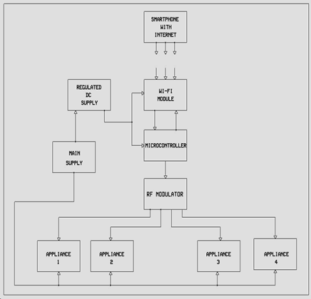
Fig.1. Block diagram of the proposed system.
Figure 1 shows the block diagram proposed system which consist of Wi-Fi module, microcontroller RF Modulator smartphone with internet and power supply’s. The microcontroller facilitates communication with other modules, including the RF module and the WiFi module. The RF module, in turn, communicates with the connected appliances. The WiFi module enables user interaction and monitoring of these appliances through a web interface accessible from a smartphone or any IoT-enabled device. This allows users to send control signals and receive feedback from the appliances remotely. All components are connected to a power supply source, with a regulated DC supply specifically used for the WiFi and microcontroller modules to ensure stable operation.
MICROCONTROLLER MODULE
A microcontroller is a diminutive integrated circuit that is purpose-built to regulate a particular operation within an embedded system. On a single device, a microcontroller typically contains a processor, memory, and input/output (I/O) peripherals. Among other devices, microcontroller units (MCU) are present in automobiles, robotics, and office equipment. With no complex front-end operating system, they are essentially basic miniature personal computers designed to control small features of a larger component. The proposed system will implement the STM32 Microcontroller.
STM32 Microcontrollers:
With the intention of optimizing the battery life cycle, STM32 microcontrollers minimize the overall power consumption of the system. Nevertheless, there are divergent specifications for applications in markets such as consumer, general portable devices, portable medical, and metering devices. While these applications necessitate low power consumption to prolong battery life, they also demand high performance for computational duties, which results in increased power consumption.
RF COMMUNICATION MODULE
Effective and dependable communication is essential to the operation of contemporary home automation systems because it facilitates smooth communication between the user interface and other system components. In this sense, the IoT-enabled RF Home Automation System’s communication module is essential as it serves as a channel for data and control signals to be sent and received inside the system. This module’s clever design makes use of Radio Frequency (RF) technologies (an RF transmitter and receiver components).
Transmitter Modules:
Schematic Diagram of a RF transmitter
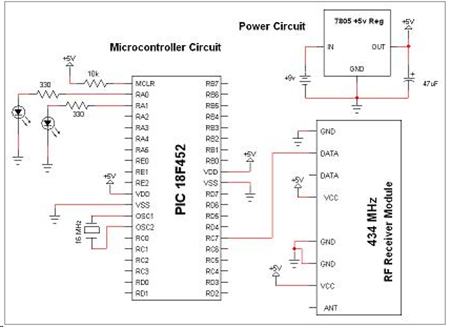
Fig. 2. Adafruit Radio Frequency Receiver Modules (Source: Google image)
Schematic Diagram of A RF receiver module
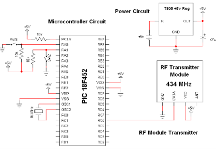
Fig. 3. RF receiver module
WI-FI CONNECTIVITY MODULE
Wi-Fi Module (for Internet Access):
Wi-Fi modules use 2.4 and 5.0 GHz radio spectrums. Wi-Fi has a range of less than 50 meters indoors and offers high-speed data transfer, easy setup, and widespread use. It’s not commonly used as the main wireless backbone in industries but is practical for making industrial machines accessible to computers and smartphones. Wi-Fi is also useful in creating internet access in public transportation vehicles.
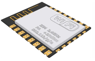
Fig. 4. Wi-Fi module.
POWER SUPPLY MODULE
12 Volts, 5 Amps Lipo Battery Pack:
A power supply module is a component or device that provides electrical power to a system or device. Its primary function is to convert electrical power from a source (such as a wall outlet or a battery) into a form that the system or device can use. Power supply modules come in various forms and configurations depending on the application, ranging from simple adapters for consumer electronics to complex units for industrial machinery or computer systems.
FLOWCHART DIAGRAM
The flowchart summarizes the system’s operating procedure. This flowchart details the sequential steps and decision-making pathways essential to the operation of the system, acting as a visual roadmap.
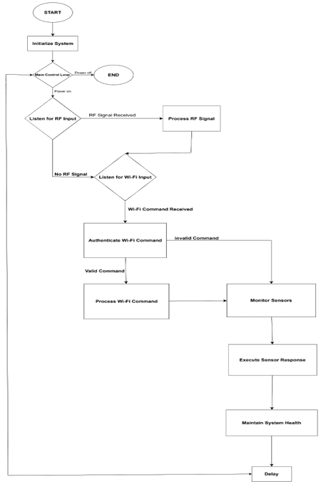
Fig.5. Flowchart of the proposed system
To implement an IoT Enabled Radio Frequency Automation System, certain requirements have to be fulfilled properly. These requirements include the following:
- The system must contain a microcontroller included in it.
- The system should contain an internal network (wires, cables, wireless).
- The system should be able to transfer data over the internet.
- The device should possess an intelligent control capability, that is, a gateway to manage the featured system.
- The system should posses a radio frequency transmitter to modulate electromagnetic waves
- The device should have a radio frequency receiver to receive and demodulate the transmitted signal and execute the instruction to the appliance concerned.
IMPLEMENTATION AND RESULTS
This research introduces a smart home automation system that enhances convenience and flexibility for the elderly, individuals with disabilities, and families with infants or pets. It eliminates the need for physical access to electrical outlets, switches, lights, and appliances, reducing stress and promoting an inclusive living environment. The system is controlled remotely using smartphones, laptops, or any IoT-enabled device with internet connectivity, providing comfort and ease of use. It is powered by a DC power supply and a battery, ensuring continuous operation, and employs a voltage regulator to deliver a stabilized 5V power supply to protect integrated appliances. The microcontroller, as the core component, establishes connections with the Wi-Fi module and the radio frequency transmitter, facilitating data exchange over the internet. The host device captures instructions from the user interface and transmits them to the microcontroller for processing, which are then modulated and transmitted to the receiver to execute the intended action.
SCHEMATIC DIAGRAM OF PROPOSED SYSTEM
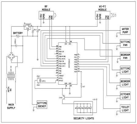
Fig. 6. Schematic Diagram
EXPLANATION OF SCHEMATIC DIAGRAM
Upon connection of a 5V power supply, the microcontroller, alongside the RF and Wi-Fi modules, initiates its startup series. This entails initializing the I/O ports, putting in place the RF and Wi-Fi modules, and establishing the necessary verbal exchange protocols. A crystal oscillator, complemented by its capacitors, presents a strong clock signal to the microcontroller, essential for accurate timing throughout the gadget’s operations.
As a monitoring hub for IoT-enabled devices, the microcontroller assesses the popularity of every linked tool, which includes the pump device, security lighting fixtures, sockets, and switches. This check ensures they’re correctly configured before operation. Control signals are relayed through the microcontroller’s I/O ports to the RF module. The RF module, in turn, translates these signals into RF commands, instructing the relay module to manage appliance power. Each appliance reacts by activating or deactivating, in line with the received command.
The system’s electronic circuitry is driven by a regulated DC supply sourced from the mains power, providing the necessary energy to the control electronics. Meanwhile, the appliances are connected via relays, strategically positioned to manage and supply power.
The system stands by continuously, awaiting input from the Wi-Fi module, which communicates signals from remote IoT devices, such as smartphones with internet connectivity. The microcontroller processes these inputs and interfaces with the RF module, operating at a 533MHz frequency, to execute the desired actions. This state of continuous vigilance is maintained as long as the power supply remains uninterrupted, with the microcontroller operational and ready to handle data at a clock speed of 11.0592MHz.
In instances where power is disrupted, the system is designed to enter a shutdown phase, ensuring that all connected devices are deactivated in a secure manner.
CONNECTION AND TESTING
A very well designed, fully automated home automation system is interconnected in accordance with the specified design. However, for the purpose of testing the prototype of this system, a four-button key fob was utilized, which was connected to the radio frequency (RF) transmitter for the purpose of transmitting RF signal commands to the receiver. Additionally, an LED was employed to represent the home appliance during the testing phase. It is important to note that the Wi-Fi module will be incorporated in due time for the final assembly of the system, as it is a delicate component.
HARDWARE COMPONENTS
Image of the RF receiver connected to the relay module with the LED as indicators for receiving the signal command.
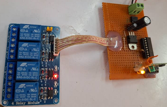
Fig.7. Relay Module and RF Receiver
The figure below shows a 4 button key fob used for the purpose of testing. This device terminal is connected to the RF transmitter Module.
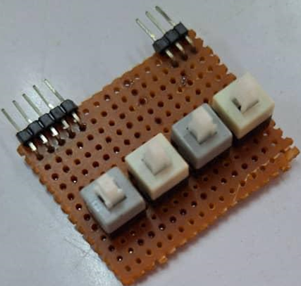
FIg. 8. A 4 button Key Fob
The diagram below shows the RF transmitter connected to the second power source. This module is connected to the Microcontroller and Wifi module.
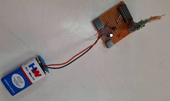
Fig. 9. RF transmitter and Power source.
Showing the WiFi module responsible for the communication with the IoT enabled device.
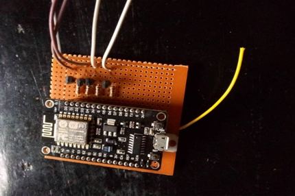
Fig. 10. WiFi Module
The Step Down transformer shown below to step down the voltage(current) from 220v to 12v.
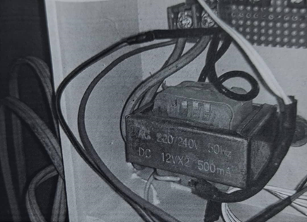
Fig. 11. Step down Transformer
Software Interface
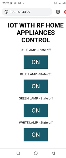
Fig. 12. Showing all systems ON.
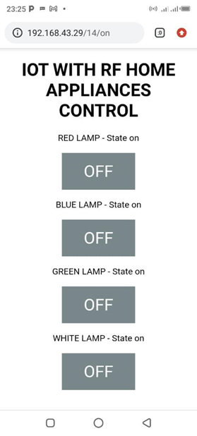
Fig. 13. Showing all systems OFF.
SYSTEM TESTING
The system establishes electrical connections by using cables to connect the apparatus to a power source. The primary controller coordinates processes. Grounds the 533 MHz receiver and its input. Connects four LEDs to the relay module, ensuring shorter ends are grounded and longer ends are connected to the relay. An additional LED is added to indicate incoming signals. The relay module manages the power supply to the LEDs. Buttons on the platform turn the LEDs on or off.
We tested the system by pressing the buttons to the corresponding LED to perform these operations:
- Put ON Light 1 “will represent the lighting system ON”.
- Put ON Light 2 “will act to utilize the home appliances ON”’
- Put ON Light 3 “will represent the sockets around the house ON”
- Put ON Light 4 “will represent Security systems ON”
- Put OFF Light 1 “will represent the lighting system OFF”.
- Put OFF Light 2 “will act to utilize the home appliances OFF”’
- Put OFF Light 3 “will represent the sockets around the house OFF”
- Put OFF Light 4 “will represent Security systems OFF”
For a Successful Operation:
- We made sure we had a stable internet connection
- To ensure uninterrupted power supply during operations, we verified that the system was appropriately connected.
- We used a distinct frequency to avoid interference.
- We tested that the 533Mhz receiver receives signals from the transmitter using an LEDs indicator.
Having conducted an analysis of the aforementioned findings, we proceed to assess their ramifications with respect to the efficacy of home automation systems and the experience of users
DISCUSSION OF RESULTS
Upon completion of the Simulation and Testing, assemble and viewing the results, we achieved our desired goals of simulating a home automation system. It conforms to the acting status of smart homes, which covers areas such as ease, comfort and flexibility.
This smart home controls four separate systems:
- The lighting system provides illumination to various parts of the house.
- The home appliance system allows users to control various appliances e.g. the water pump.
- The sockets provide smart control to devices that do not possess any automation properties.
- The Security system to help provide security throughout the whole day and night.
The integration of the four systems to any kind of home or flat is highly beneficial. There are lots of supporting factors for utilizing this system in a practical environment. Through this procedure, users can easily control all home appliances with limited efforts and limited expenses compared to other home automation technologies. Some of these merits include:
- Integrating the WiFi module improves on the ease of operation and comfort enabling the user to control these appliances from anywhere in the world, so far the system is connected to a stable internet and steady power supply.
- Wireless radio frequency systems make the home system safe to use.
- User does not need to give any extra physical effort to turn on or off any appliance like lights or water pump.
- It makes it possible to control electronic devices without using ordinary switch boards which makes the room visibly more attractive.
- Through this process users also can save some energy than a normal switch controlled board.
SUMMARY
With the progression of technological advancements, residential dwellings are becoming increasingly intelligent. Integrating Internet of Things (IoT) technologies into Radio Frequency (RF) automation systems enhances the system’s intelligence, affordability, and energy efficiency. The primary method employed in this system involves utilizing automation to regulate and develop a suitable design for the system, with the ultimate goal of establishing a smart home. The implementation of the four systems in this study empowers the home with intelligence, eliminating the need for physical human effort. Power supplies provide energy, while the lighting and security systems contribute to maintaining a sustainable environment by ensuring illumination and safety. The utilization of the system to control home appliances empowers users to exert control over the appliances and monitor their status (On or OFF). Through a meticulously designed smart control mechanism, the system effectively reduces energy costs for the users.
RECOMMENDATION
The study presents a cost-effective and energy-efficient handheld portable smart phone system. It offers remote control of appliances using a Wi-Fi module and RF automation, providing an extended range for communication. The system is particularly beneficial for busy urban users. To improve the system, a fully Wi-Fi-based communication system is suggested, which would enhance security, increase data throughput, and allow the integration of security cameras for live video streaming.
LIMITATIONS OF THE STUDY
This system provides convenience and efficiency to the users, however comes with some limitations like:
- With the advancement in technology, the RF module system may be vulnerable to security attacks. Hackers may use Jammers or Replays to either stop the user from carrying out an instruction or replay a signal to perform an unauthorized action on the appliances.
- This system is dependent on stable internet connectivity for long range interaction with the system and the appliances.
- The system requires a constant power supply be supplied throughout the system unlike the manual switches that can be flipped even without power supply
REFERENCE
- Ali, S. M. M., Augusto, J. C., Windridge, D., & Ward, E. (2022). A user-guided personalization methodology to facilitate new smart home occupancy. Univers Access Inf Soc, 1-23. doi: 10.1007/s10209-022-00883-x.
- (n.d.). Radio-frequency identification (RFID) | Technology, History, & Applications. Retrieved November 27, 2023, from https://www.britannica.com/technology/RFID
- Cristian, Lazaroiu., Mariacristina, Roscia. (2021). BLE To Improve IoT Connection in the Smart Home. doi: 10.1109/ICRERA52334.2021.9598622
- Domb, M. (2019). Smart Home Systems Based on the Internet of Things. In Y. Ismail (Ed.), Internet of Things (IoT) for Automated and Smart Applications. DOI: 10.5772/intechopen.84894.
- Edu, J. S., Such, J. M., & Suarez-Tangil, G. (2020). Smart home personal assistants: a security and privacy review. ACM Computing Surveys (CSUR), 53(6), 1-36.
- Giri, N., Gupta, C., Chiothwani, M., & Gidwani, P. (2018). Home automation using panoramic images using IoT.
- Huraj, L., Šimon, M., & Horák, T. (2020). Resistance of IoT Sensors against DDoS Attack in Smart Home Environment. Sensors, 20(18), 5298. https://doi.org/10.3390/s20185298
- (2023, June 16). What is automation? Retrieved November 27, 2023, from https://www.ibm.com/topics/automation?mhsrc=ibmsearch_a&mhq=what%20is%20automation
- Jabbar, W. A., Kian, T. K., Ramli, R. M., Zubir, S. N., Zamrizaman, N. S., Balfaqih, M., … & Alharbi, S. (2019). Design and fabrication of smart homes with Internet of Things-enabled automation systems. IEEE Access, 7, 144059-144
- Saha, S., Ishraque, H., Islam, M. T. U., & Rahman, M. A. (2019). IoT based smart home automation and energy management(Doctoral dissertation, Brac University).
- Shah, A. S., Nasir, H., Fayaz, M., Lajis, A., & Shah, A. (2019). A review on energy consumption optimization techniques in IoT based smart building environments. Information, 10(3), 108.
- Singh, A. K., Firoz, N., Tripathi, A., Singh, K. K., Choudhary, P., & Vashist, P. C. (2020). Internet of things: From hype to reality. In An industrial IoT approach for pharmaceutical industry growth(pp. 191-230). Academic Press.