Aspen HYSYS’ Simulation of Ammonia Synthesis from Stranded Gas
- Ugo Nwitte-Eze
- Charles Ifeanyi Ugwu
- 1-16
- Mar 27, 2024
- Education
Aspen HYSYS’ Simulation of Ammonia Synthesis from Stranded Gas
Ugo Nwitte-Eze1, Charles Ifeanyi Ugwu2
1Department of Chemical Engineering, Federal University of Technology, PMB 704, Akure, Ondo State, Nigeria.
2Department of Chemical Engineering, Alex Ekwueme Federal University Ndufu Alike, Ebonyi State, Nigeria
DOI: https://doi.org/10.51584/IJRIAS.2024.90301
Received: 19 February 2024; Accepted: 22 February 2024; Published: 27 March 2024
ABSTRACT
Companies have been finding ways stranded gas can economically be used or marketed rather than flaring it. The issue of gas flaring is being frowned upon by many regulatory bodies; hence most oil and gas operators are advised to find a better alternative. A high rate of gas flaring threatens our environment as it reduces the oxygen content in the atmosphere resulting in health issues and waste of our natural resources. However, this paper aims to simulate ammonia production from stranded gas (gas flare stream). A simulation approach was adopted using Aspen HYSYS V10 (Version 10). Three basic processes were employed during the simulation: steam reforming, carbon capturing and ammonia synthesis. The data used for the simulation were obtained from a marginal field operator in the Niger Delta region of Nigeria. Upon simulation, it was observed that the gas stream flowing at a rate of 484.13MMscf/day, with a pressure of 568.9 psig, yielded high ammonia gas of0.810829276 mole fraction at a low temperature of 30oC and pressure of 298.62 bar. High purity of hydrogen and 0% yield of carbon (IV) oxide were obtained by passing the syngas through carbon capture unit which made of absorber and desorber of packed column and MEAmine solvent for removal of CO2. In a nutshell, the result obtained from the simulation proved to be environmentally friendly as little to no greenhouse gases were expended.
Keywords-ammonia production; ASPEN HYSYS simulation; gas utilization;MEAmine solvent; stranded gas; syngas production.
INTRODUCTION
Natural gas is considered stranded when it cannot be used due to economic and logistical issues. This can be due to its minute quantity or far distance from fairly large population centres to be developed economically. The excess gas reserve can also be stranded gas when it leads to an excessive market supply [1]. According to World LNG/GTL, there is more natural gas than the world has consumed to date, and the question is, “how can we help solve this problem, and how can we help bring more stranded gas to market?” [2]. Unless natural gas is made available from the wellhead to customers who might be at a remote distance from the source, its worth is little. Natural gas transport is expensive because of its low Energy per unit volume. Companies have been finding ways to use or market stranded gas economically rather than flaring.
Many researchers have investigated several means by which this stranded gas can be put into use [3-7]. These include converting the gas to liquid for easy storage and transportation, compressing natural gas to less than 1% of its volume, making antifreeze, plastics, pharmaceuticals and fabrics. It is also a good feed for ammonia synthesis, which is used in the manufacturing of fertilizer and other useful products. In order to solve the issue of greenhouse gas emissions in the maritime industry, ammonia has become a promising fuel for the industry because it is environmentally friendly [8].
Production of ammonia
Steam reforming, partial oxidation, autothermal reforming and water electrolysis are some of the processes use in the production of synthesis gas. The hydrogen produced will react with nitrogen to yield ammonia. The ammonia produced can be used for fertilizer (Urea) production, in power generation, as fuel for vehicles, gas- turbine plants and as a cooling agent [9-15]. In the ammonia synthesis, nitrogen is reacted with hydrogen in a stoichiometric ratio of 1:3 to yield ammonia giving rise to no by-products. Sources of hydrogen include heavy fuel oil, coal,Naphta and other light hydrocarbons such as Refinery off-gases and LPG [16]. Natural gas contains fewer impurities, high hydrogen to carbon ratio and less percentage of higher hydrocarbons. Nitrogen needed for ammonia synthesis can be obtained from air. The technology of partial oxidation has the uniqueness of producing syngas from heavy hydrocarbons. Using relatively high space velocity, partial oxidation offers the benefit of giving high conversion of methane with excellent selectivity for hydrogen [17]. It can be a catalytic or non-catalytic process that occurs by partially combusting heavy hydrocarbons. Catalytic partial oxidation makes use of catalysts for its reaction process. Carbon deposition using this technique has been discovered to cause increase in catalytic deactivation, damage the active phase and formation of inactive spinel phases.
In Coal gasification, coal is gasified underground and the syngas which contains majorly hydrogen and carbon monoxide is sent to the surface for processing at the syngas cleaning unit. The yielded hydrogen then reacts with nitrogen to produce ammonia [18]. Water electrolysis uses electricity from renewable energy resources such as solar Energy, ocean energy and wind energy for hydrogen production hence its sustainability and advantage over other techniques for hydrogen production [19-25]. Different electrolytes such as alkaline water electrolysis, proton exchanges membrane, alkaline anion exchange membranes and solid oxide electrolysis have been adopted for this technique. In the study of [24], he concluded that this technique has simple process, eliminates pollution issues, gives high purity hydrogen production and is sustainable whilst[25] in their work disclosed that the gas evolution rate is lowand has high consumption of energy. The bulk of the world’s ammonia production is based on steam reforming.
Steam reforming
Steam reforming uses catalysts in producing synthesis gas from light hydrocarbons such as Natural Gas, Naphta, Refinery off-gases or LPG [16]. This technique is most commonly used, and it is of industrial scale [26-28]. Purification of natural gas (desulphurization), Hydrogen production (reforming), Conversion of CO to CO2 (shift conversion), CO2 removal and Separation of oxygen are the major steps involved in the synthesis gas production.
Removal of CO2 can be achieved using the Benfield process, catacarb process, amine wash, glammarco-vetroco process, methanation or pressure swing adsorption. The first four do not achieve the total elimination of carbon (IV) oxide. Methanation removes trace amounts of CO from synthesis feed mixtures rich in H2. The process converts carbon oxides to methane and water [29, 30]
![]()
Pressure Swing Adsorption (PSA) separates gases by regenerating adsorbents through rapid reduction of partial pressure of the adsorbed component either by lowering the total pressure or using a purge gas. Methanation reactions are exothermic and require heat removal, it leaves the syngas with a concentration of about 50 ppm of CO and CO2, which is still poisonous to ammonia synthesis catalyst. PSA ensures pure hydrogen is obtained, leaving the syngas with no impurities. Hence, this process (PSA) eliminates the need for methanation [29]. A recent work by Hongwei [31] showed the removal of 85% CO2 from the syngas, 98.2% H2S and 100% NH3. However, this technique did not assure 100% removal of CO2 as some traces of CO2 are still left behind, with Aspen HYSYS using pressure swing adsorption with many adsorbers guarantees this 100% removal of CO2.
Oxygen is separated from air using pressure swing adsorption, membrane or cryogenic systems. Pressure swing adsorption uses a two-stage concentration with Carbon Molecular Sieve (CMS) for the first stage and zeolite for the second stage. The arrangement can be altered but not preferable for efficiency. Argon, non-inert gas, and N2 and O2 are passed through CMS bed which absorbs N2 and O2. Then, the absorbed N2 and O2 are collected and taken to the zeolite stage, where N2 is removed by selective adsorption leaving behind pure O2 [29]. The cryogenic system is the most complex system of nitrogen generation but produces high purity nitrogen. It uses a compression devise to capture ambient air into thedistillation setup. The air is cooled to about 10oC and passed through a series of filters to remove impurities. Finally, the clean air is expanded at the heat exchanger causing the temperature to fall below its condensation point and liquefy, resulting in the distillation of pure nitrogen. Birendra et al. [32] performed an economic analysis on the three major systems of extracting nitrogen from the air and stated that a double staged membrane process with a selectivity of 5.5 and a membrane of 1000 GPU has a cost of gas production of US$0.05/kg for 90% pure oxygen, which is lower than pressure swing adsorption and cryogenic distillation, which only meets its cost targets at a much larger scale.
Hydrogen production equations are expressed as follows:
![]()
The desired end-product ammonia is produced by catalytically reacting hydrogen with nitrogen (derived from process air) in a stoichiometric ratio of 3:1 to form anhydrous liquid ammonia. This step is known as the ammonia synthesis loop (also referred to as the Haber-Bosch process).
Ammonia equation
![]()
Researchers such as [16, 33] reviewed that steam reforming is preferable due to its energy efficient technology, low temperature at the adiabatic pre-reformer unit that increases the production capacity, obtainable industrial scale production and achievable reduced size reformer furnace when the adiabatic pre-reformer unit operates at a low temperature. This technique currently is still not proven an efficient technique for a hydrocarbon containing sulphur; therefore, the hydrocarbon has to be desulphurized before syngas production which requires a large amount of energy inputs because it is highly endothermic. When carbon and soot formation reaction occurs, it leads to catalyst deactivation, an increase in pressure drop and a reduction in reaction rates leading to serious heat transfer problems and tube damage [34].
Ammonia synthesis has been achieved through direct electrochemical conversion of nitric oxide (NO). [35] used Fe2O3nanorods as electrocatalyst for the NO reduction reaction to produce NH3 under ambient conditions. In the ammonia synthesis performed by [36] through electrochemical reduction of nitrate enabled by NiCo2O4 nanowire array on carbon cloth, shows an efficient way of producing ammonia. The result shows that 0.1 M NaOH solution with 0.1 M NaNO3 indicates that NiCo2O4/CC was able to yield a high Faradic efficiency of 99.0% and NH3 of 973.2 µmol-1cm-2.
A study carried out by [37] shows that low carbon ammonia can be synthesized using cold energy utilization of liquefied natural gas regasification which can augment energy utilization efficiency of synthetic ammonia.
With the available techniques in producing ammonia, the industry still faces the challenge of greenhouse gas emission through the emission of carbon oxides. Yusuf Biceret al. [18] presented a paper on greenhouse gas emission of different ammonia production techniques. It was reported that coal-based electrolysis method was equivalent to 13.6kg CO2 per kg while nuclear-based electrolysis produced 0.48 kg CO2 per kg. The result was a worrisome indication that calls for more work to be done to combat carbon oxides emission.
Hence, this work aims at simulating ammonia production from stranded gas (gas flare stream) using Aspen HYSYS V10. Green ammonia was produced through the use of nitrogen separated from the air as a renewable energy. The model eliminates carbon (IV) oxide production to zero percent and yields high ammonia production. Zero percent carbon (IV) oxide production helps in eliminating greenhouse gas emission to the environment.
MATERIALS AND METHODS
In this study, Aspen HYSYS V10 was used to simulate ammonia synthesis, which comprised two basic parts: syngas and ammonia production. The data used for this study was sourced from a marginal field operator in the Niger Delta region of Nigeria. In the simulation process, natural gas (LP-ws) was used as a feedstock for syngas production. The composition of the natural gas is illustrated in table 1 a sweet gas, remains the same after the purification of the natural gas. In this study, nitrogen was used as a feed for ammonia synthesis, thereby eliminating the need for the second reformer stage. The pre-processed nitrogen used as feed stock was separated from air which is a renewable energy source. The natural gas feed (LP-ws) was pre-processed and used as feed for the syngas production. Hydrogen was extracted from methane at high temperatures, after which nitrogen and hydrogen were catalytically reacted to make ammonia at a low temperature and high pressure. Carbon (IV) oxide was removed at the carbon capture unit which made use of absorber and desorber of packed column to ensure sufficient surface area for the absorption of CO2 [38]. MEAmine was employed as the solvent for effective removal of CO2 while lean amine was regenerated for continuous cycle. The decarbonized gas was used as a feed for the ammonia synthesis unit.
The composition of the feed gas to be used for the ammonia gas production plant is illustrated in Table 1. The stranded gas emanating from Field X in the Niger Delta region also exhibited the following properties:
| S/N | Properties | Measurement |
| 1 | Flowrate | 484.13MMscf/d |
| 2 | Pressure | 568.9psi |
| 3 | Temperature | 109oF |
Table 1 Raw data with gas composition
Software equipment
- Steam reformer
- Water gas shift
- Separator
- Heaters
- Coolers
- Carbon capture
- Ammonia converter reactors
Process description
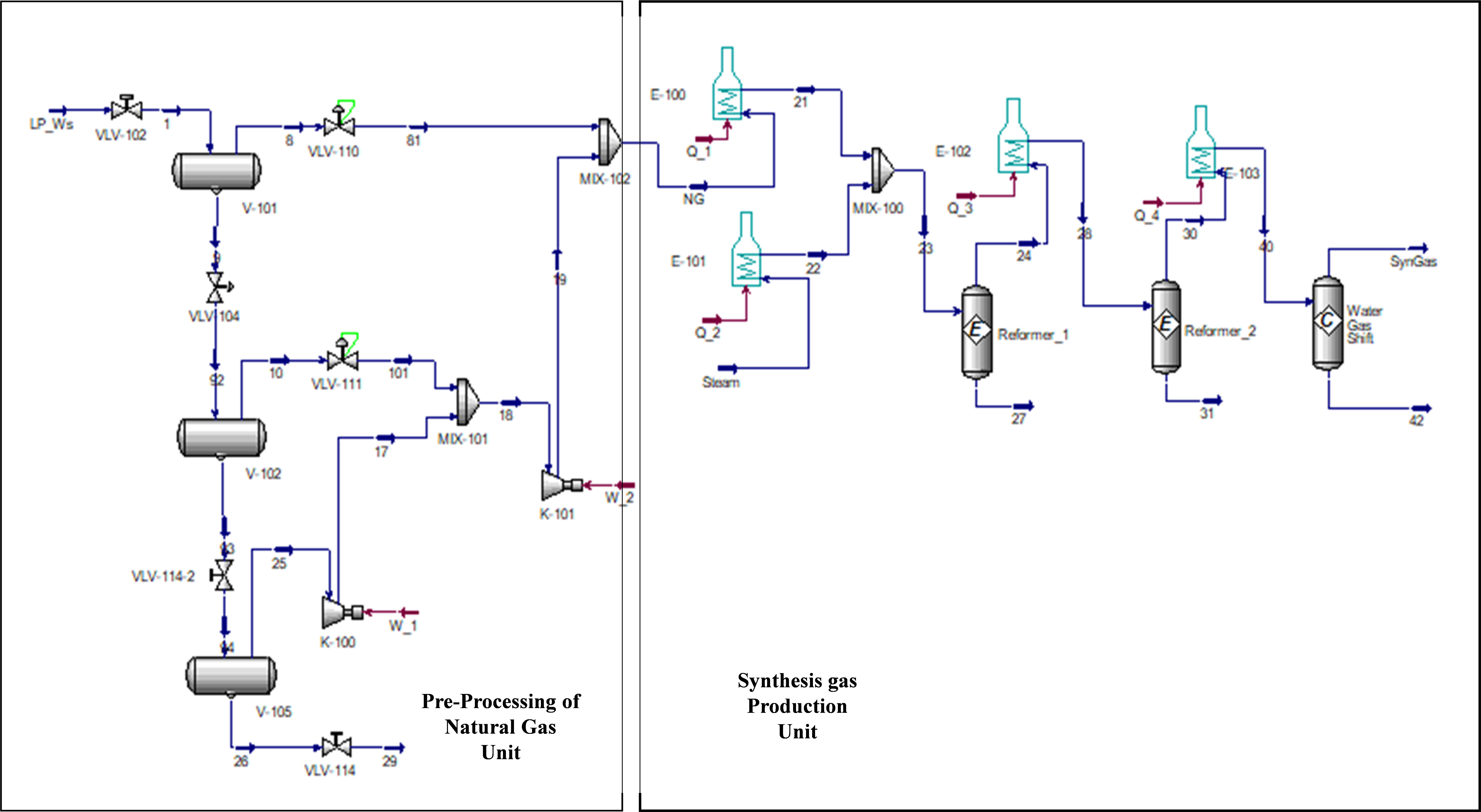
Aspen HYSYS uses two major parts in ammonia synthesis: the production of syngas and the production of ammonia. Syngas production process uses the heater, the reactor and the water gas shift. Carbon capture unit was used to decarbonize the syngas before ammonia synthesis meanwhile, ammonia production involves using the Haber process. The process flow diagram of the simulation performed in this study is indicated in Fig. 1.
Figure 1. Pre-Processing of the natural gas and Syngas production
Hydrogen production
This process produce hydrogen from natural gas in the steam reformer at high temperature. The natural gas which was first pre-processed to boost up the methane was used as feed for the syngas production. Steam is heated up at the heater, which flowed to the mixer as stream 22 at a temperature of 1500oC and mixed with processed natural gas which entered the mixer as stream 21 at the same temperature range. The mixed product left the mixer as stream 23 at a temperature of 1499.89oC and entered the first reactor. The product from the first reactor (stream 24) was further heated to maintain the high temperature from the first heater before transferred to the second reactor. The reaction at the steam reformer was in the presence of nickel catalyst to yield hydrogen, carbon monoxide and carbon (IV) oxide. Fig. 4-5 give the compositions of the streams at the synthesis gas production unit.
Reformer_1 and Reformer_2:
![]()
Water gas shift
At the water gas shift, CO reacts with the steam to produce CO2 and H2. Carbon monoxide is poisonous to the ammonia synthesis catalyst and thus must be removed. Carbon monoxide is first converted to carbon (IV) oxide and removed at the absorbent. Water gas shift reaction serves as the intermediate step in enriching hydrogen production and reducing CO in the synthesis gas [39]. Reaction at water gas shift reactor requires catalyst for effective of production of hydrogen. This work employed layered double hydroxide-derived copper (LD-CU) as catalyst for the reaction which was reviewed by [40] to perform well even at low temperature range. Stream 40 served as the feed for water gas shift in the presence of LD-Cu to convert CO to CO2 to yield more hydrogen.
![]()
Carbon capture
Figure 2: Carbon capture unit
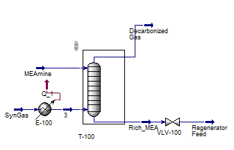
Carbon capture is the technique for removing CO2 from the syngas. It uses absorber of packed column to ensure sufficient surface area for the absorption of CO2. The syngas enters at the bottom of the absorber with the lean MEAmine solvent (amine stream that is stripped of CO2) entering at the top of the absorber [38]. As the MEAmine stream leaves the bottom of the absorber, it is loaded with CO2 known as rich MEAmine. The amine stream is usually introduced on the second stage from the top with make-up water entering at the first stage. This allows the first stage to function as a water wash to remove any entrained MEA that may be carried out along with the decarbonized gas that is stripped of CO2. The rich stream from the absorber exchanges heat with the lean stream from the desorber at the cross heat-exchanger enabling the rich stream to be heated and the lean stream to be cooled down. The lean MEAmine is then regenerated and the temperature lowered before using as the feed for the next recycle. Fig. 2 displays the flow diagram of the carbon capture unit.
Ammonia synthesis
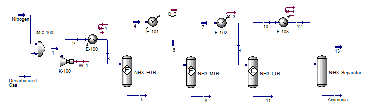
The syngas from carbon capture unit was mixed with a feed gas of nitrogen at the mixer. The mixed products were passed through different temperature reactors (high, medium and low temperature reactors) to ensure high-quality ammonia yield. After the reaction at the high temperature reactor, the temperature of the feed was brought down to cool before been transferred to the medium temperature reactor. The feed temperature was further lowered before been transferred to the low temperature reactor and finally separated at the separator. The temperature and pressure were altered until the optimum yield was made. Nitrogen reacted with hydrogen in the stoichiometric ratio of 1:3 to form ammonia gas. Fig. 3 depicts the process flow diagram for ammonia synthesis.
![]()
Figure 3. Process flow diagram (PFD) for ammonia synthesis
Description of steps for Ammonia plant simulation
The procedures for simulating an ammonia gas plant in Aspen HYSYS are described as follows:
- Selection of component list
- Selection of fluid package
- Defining reactions and formation of reaction sets
- Installing the feed streams
- Drawing the flow sheet.
Selection of component list
The reactants component list for this simulation was based on the raw data from the gas flare stream. Each component is displayed in Table 1.
Selection of fluid package
The fluid package for this work is Peng Robinson PR. This fluid package is the most enhanced model in Aspen HYSYS [41].
Defining reactions and formation of reaction sets
This work made use of a series of reactions such as steam reforming, high and low shift conversion, pressure swing adsorption and ammonia conversion.
Installing the feed streams
The feeds for steam reformer were natural gas and steam. In the ammonia conversion reactor, syngas and nitrogen were fed into the reactors. Fig. 4-7 show the feeds of each component and their properties.
RESULTS AND DISCUSSION
Ammonia production was made by reacting syngas with nitrogen at the ammonia conversion reactor at the stoichiometric ratio 3:1. The syngas was produced at the steam reformer and passed through treatment stages before taken to the ammonia conversion reactor. In order to obtain high quantity of ammonia, the syngas was passed through different reactors altering the operating conditions.
Pre-Processing of Natural Gas
Natural gas (LP-ws) was first pre-processed at this unit before hydrogen synthesis. This was done to increase the yield of low hydrocarbon and lowers the high hydrocarbon. The LP-ws was passed through three different stages processing to ensure high quantity of low hydrocarbon obtained. Stream 1 with 0.8455 mole fraction of methane entered the first processor where the initial process took place resulting to 0.868234 mole of fraction of methane, little increase in the mole fractions of CO2, nitrogen and ethane while the mole fractions of C3+ dropped. Stream 9 which was entrapped with unreacted gases was taken to the second processor for further processing. At the second processor 0.865869 mole fraction of methane was obtained with still increase in the mole fractions of CO2, nitrogen and ethane while mole fractions of C3+ further dropped. The feed (stream 94) for the third processor with entrapped gases and 0.148137 mole fraction of methane was processed yielding to stream 25 with 0.860556 mole fraction of methane, much more increase in the mole fractions of CO2, nitrogen and ethane with more reduction in the mole fraction of C3+. The pre-processing natural gas unit caused more methane to be produced from 0.8455 mole fraction of the feed to 0.868229 mole fraction of the pre-processed natural gas which served as the feed for the steam reformer. Fig. 4 displays the mole fractions of the natural gas composition.
Figure 4. Composition of natural gas and LP-ws at the pre-processing unit
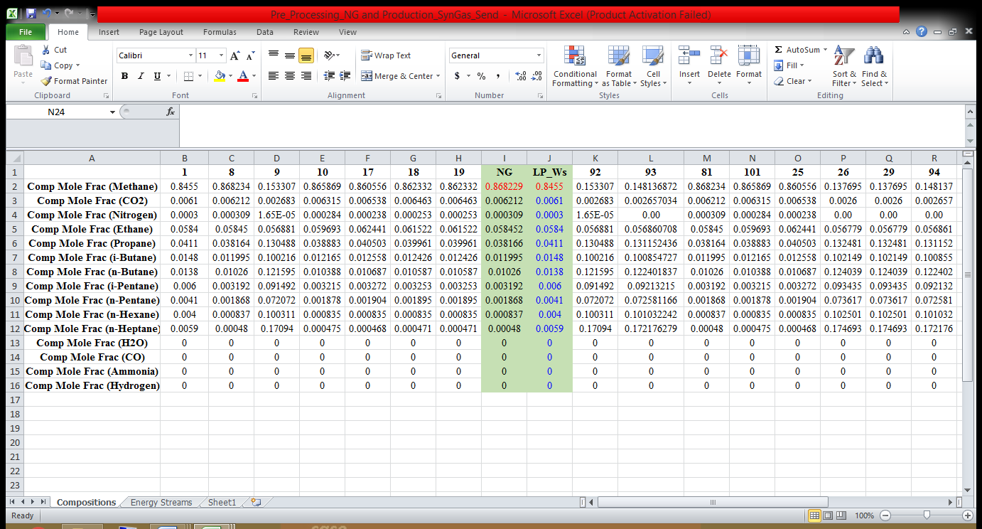
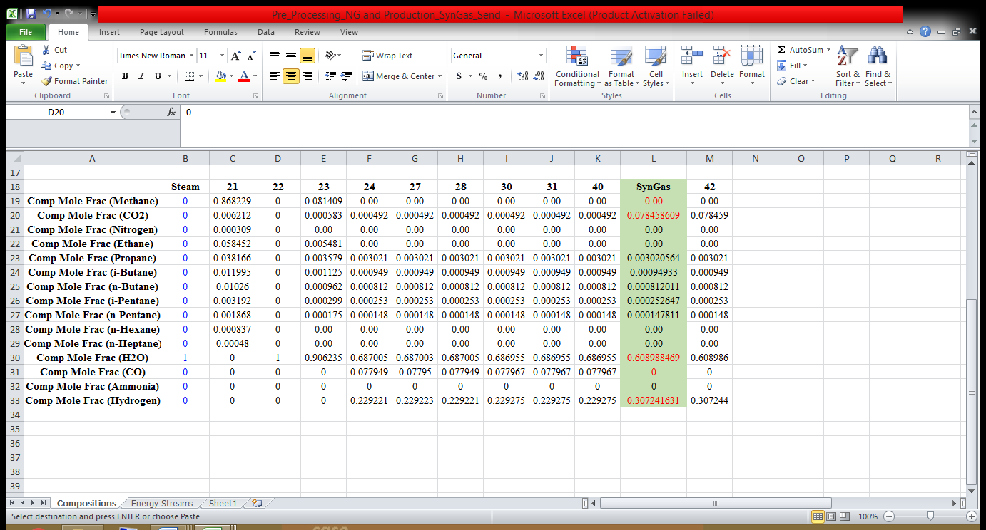
Syngas Production
At the steam reformer, the pre-processed natural gas and steam were fed into the reformer in the presence of a nickel catalyst. The pre-processed natural of 0.868229 mole fraction was first heated to a temperature of 1500oC with corresponding pressure of 27.66 bar before mixing with the steam of the same temperature range and pressure range. The feeds were first heated to the same temperature range before mixing them at the mixer as stream 21 and 22, this was done to ensure equilibrium balance between the products. The mixed product (stream 23) which serves as feed for the first reactor left the mixer at temperature of 1499.89oC, pressure of 27.66 bar and molar flow rate of 5002.59 MMSCFD with 0.000583 mole of CO2. The reaction at the first reactor yielded stream 24 with 0.229221 mole fraction of hydrogen, 0.000492 mole fraction of CO2, 0.077949 mole of CO, at molar flow rate of 5926.52 MMSCFD. After the reaction at the first reactor, the product (stream 24) at a temperature of 1121.01oC was heated up back to 1500oC before taking to the second reactor. The process at the second reactor resulted into stream 30 with 0.229275 moles fraction of hydrogen, 0.000492 mole fraction of CO2, 0.077967 at molar flow rate of 5926.77 MMSCFD, temperature of 1499.90oC and pressure of 27.31 bar. The difference between the quantities of hydrogen and carbon monoxide at the first and second reactors shows that there was more formation of CO and H2 at the second reactor. The feed (stream 40) for water gas shift entered the component at the temperature of 1000oC, pressure of 26.97 bar and molar flow rate of 5926.77 MMSCFD. At the water gas shift component, CO reacted with the steam to yield CO2 and more hydrogen. The reaction at the water gas shift yielded 0.307242 mole fraction of hydrogen and 0.078459 mole fraction of CO2, 0.00 mole fraction of CO at the temperature of 1059.65oC, pressure of 26.97 bar and molar flow rate 5926.77 MMSCFD. The high increase in the mole fraction of H2 and CO2 shows that CO conversion yielded more H2 and CO2 at the water gas shift while CO was completely reduced to zero mole fraction.
Figure 5. Composition of synthetic gas produced from steam reforming process
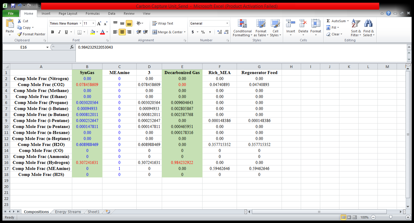
At the carbon capture unit, the syngas was used as feed whilst melamine was used as the solvent. The syngas of high temperature 1060oC was lowered to 65oC at the cooler as stream 3 with corresponding pressure of 2.5 bar before flowing to reaction unit. After the reaction at the carbon capture unit, the decarbonized gas was left with 0.00 mole fraction of CO2 while 0.04740893 mole fraction of CO2 was left unreacted which was entrapped with rich MEA. The rich MEAmine from the absorber was then taken to the heat-exchanger from where it exchanges heat with lean amine. The lean MEAmine was regenerated as feed for the carbon capture unit for another cycle of decarbonization. The regenerated amine at high temperature was also lowered to 65oC before the recycle of decarbonization. The reaction at this unit resulted into more production of hydrogen from 0.307241631 mole fraction from the syngas to 0.984232922 mole fraction.
From Fig. 6, it is shown that pure hydrogen gas of 0.984232922 mole fraction was obtained, and carbon (IV) oxide was at 0% leaving nitrogen gas and other C4+ in negligible amount. The material streams at different process units with their operating conditions are indicated in Appendix A (Fig. A.1-A. 3).
Figure 6. Composition of the material streams at carbon capture unit
Ammonia synthesis
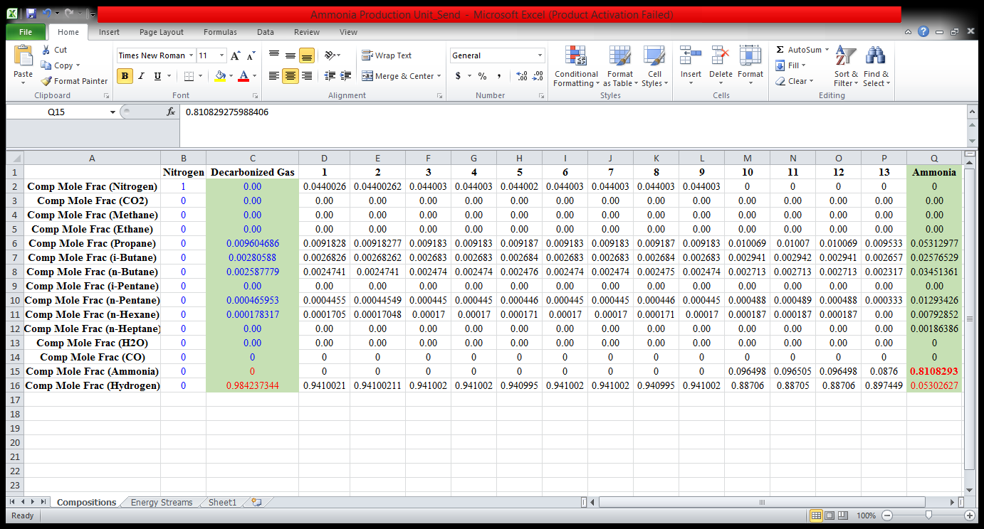
The decarbonized gas from the carbon capture unit and nitrogen were the feeds for ammonia synthesis. The decarbonized gas of 0.984232922 mole fraction of hydrogen with zero mole fraction of CO2 was mixed with nitrogen at mixer which left the mixer as stream 1. The temperature of the stream was further raised before being introduced to the high temperature reactor (HTR) as stream 3. To guarantee high-quality ammonia manufacturing, the streams were fed into various reactors at various temperatures while maintaining roughly the same pressure and flow rates. The stream 4 from the high temperature reactor at the temperature of 1200oC, pressure of 299.66 bar and molar flow rate of 1935 MMSCFD was passed through the cooler to lower the temperature of the stream to fit into the medium temperature reactor. The quantity difference between the mole fractions of nitrogen were minimal, as can be seen from the material stream composition in fig. 5, necessitating additional reaction at a lower temperature. After the reaction from the medium-temperature reactor, the temperature of stream 7 was further dropped at the cooler to reach a temperature suitable for the low-temperature reactor. At a molar flow rate of 1935 MMSCFD, stream 9 from the cooler was fed into the low-temperature reactor at a lower temperature of 500oC. This reactor produced a considerable amount of ammonia and reduced hydrogen, yielding mole fractions of ammonia and hydrogen of 0.096498 and 0.88706, respectively. The stream 9 from the cooler at a lowered temperature of 500oC was fed into the low temperature reactor at a molar flow rate of 1935 MMSCFD. There was a significant yield of ammonia and reduction of hydrogen at this reactor resulting to 0.096498 and 0.88706 mole fraction of ammonia and hydrogen respectively. To obtain the optimum yield of ammonia, the stream 9 from the low temperature reactor was further lowered to a reasonable low temperature of 30oC as stream 12. This caused more ammonia to be obtained at the separator resulting to 0.8108293 mole fraction. Fig. 5 shows the material stream composition from the ammonia synthesis unit.
Therefore, the high yield of ammonia gas can be attributed to the low temperature of nitrogen and hydrogen fed into the conversion reactor at a temperature of 30oC. This condition corresponded with the Aspen HYSYS simulation of ammonia gas plant designed by Nabil et al. [41] which reviewed that the increase of feed temperature (hydrogen and nitrogen) causes a decrease of ammonia production rate. High purity of hydrogen and 0% yield of carbon (IV) oxide after decarbonization at the carbon capture unit can be ascribed to numerous absorbers used [27 18]. The composition of ammonia gas produced is shown in fig. 7.
Figure 7.Composition of ammonia gas produced from the Haber process
The equilibrium reaction for NH3_HTR, NH3_MTR and NH3_LTR is the same.
![]()
The equilibrium reaction is governed by the Gibbs energy equation, given as:
![]()
Where:
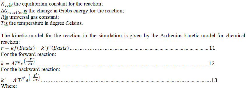
Where:
Basisis methane component. Methane was selected as the basis for the kinetic model, since it has the highest mole fraction in the processed natural gas.
AandA‘ are the Arrhenius constant for the forward and backward reaction.
EandE’ are the activation energy for the forward and backward reaction
Ris the gas universal constant
Tis the temperature of the reaction in Kelvin.
CONCLUSION
Companies have been driven to develop alternatives to flaring in the hunt to find a market for stranded gas. Using Aspen HYSYS V10, it was inferred that a gas flare stream of 484.13 MMscf/d, at temperature of 109oF, and a pressure of 568.9 psi produced ammonia gas with mole fraction of 0.8108293 and hydrogen with a mole fraction of 0.984232922. The process comprised of production of syngas and production of ammonia. After decarbonization, the steam reforming process, which was utilised to produce syngas, produced high pure hydrogen at an optimal yield of 0.984232922 moles fraction with 0% carbon (IV) oxide. The optimum yield of ammonia gas of 0.8108293 mole fraction was obtained at a low temperature of 30oC and pressure of 298.62 bar at a stoichiometric ratio of 1:3 of nitrogen and hydrogen. This ammonia synthesis from natural gas (gas flare stream) can resolve the problems associated with gas flaring and provide solutions to the dilemma of how stranded gas can be made profitable. The ammonia conversion reactor feed (nitrogen and hydrogen) had a low temperature, which contributed to the high rate of ammonia production. High purity of hydrogen and zero yield of carbon (IV) oxide were obtained by flowing the gas through carbon capture unit of several packed column with MEAmine as solvent. In a nutshell, the result obtained from the simulation proved to be environmentally friendly as little to no greenhouse gases was expended during ammonia production.
Funding sources
This research received no external funding.
Conflicts of interest
There are no conflicts of interest to declare.
REFERENCES
- M.F. Chaberlie, and Rojey, “A. Prospects for exploiting stranded gas reserves”, Gastech,Conference,Houston, TX, 2000
- WorldLNG/GTL,”World LNG/GTL Review”. Houston, Texas : Zeus Development Inc. 2001.
- Arno, De Klerk,”Gas-to-liquids conversion”,National gas conversion technologies workshop of ARPA-E US, Houston TX 13, Department of Energy,January 13, 2012. arpa-e.energy.gov
- E.A.Jose, Graciano, Benoit, Chachuat, and Rita MB, Alves, “Conversion of CO2-Rich Natural Gas to Liquid Transportation Fuels via Trireforming and Fischer-Tropsch Synthesis”ACS Publications, Industrial & Engineering Chemistry Research, Vol. 30, pp. 9964-9976, 2018. https://doi.org/10.1021/acs.iecr.8b00135
- A.David, Wood, Chikezie, Nwaoha and F.Brian, “Gas-to-liquid”Journal of Natural Gas Science and Engineering,Towler, pp. 196-208, August 9, 2012.
- Muhammad, Imran Khan, Tabassum, Yasmin and Abdul, Shakoor,”Technical overview of compressed natural gas (CNG) as a transportation fuel”, Renewable and Sustainable Energy Reviews, Elsevier. Vol. 51, pp. 785-797,2015. https://doi.org/10.1016/j.rser.2015.06.053
- J.Ernest, Moniz, et al.,”The Future of Natural Gas”, Electric Power Research Institute,Cambridge.2011.
- Michail, Cheliotis, et al., “Review on the Safe Use of Ammonia Fuel Cells in the Maritime Industry”, Energies,Antonino S.Arico, vol14 (11), pp.3023, May 23, 2021.https://doi.org/10.3390/en14113023
- E. Kroch, “Ammonia-a fuel for motorbuses”, J Inst Petrol,vol. 31, pp. 213–223,1945
- N.Iki, O. Kurata et al.”Micro Gas Turbine Firing Kerosene and Ammonia”, America Society of Mechanical Engineers, August 12, 2015. https://doi.org/10.1115/GT2015-43689
- S .E.l. May, I. Boukholda, and A.Bellagi,”Energetic and exergetic analysis of a commercial ammonia water absorption chiller”, International Journal of Exergy,vol.8 (1), pp.33-50, 2011 https://doi.org/10.1504/IJEX.2011.037213
- A.J.Reiter, and S-C.Kong, “Combustion and emissions characteristics of compression-ignition engine using dual ammonia-diesel fuel”, Fuelvol.90 (1), pp.87-97, 2011https://doi.org/10.1016/j.fuel.2010.07.055
- F-FLi, and S.Licht,”Advances in Understanding the Mechanism and Improved Stability of the Synthesis of Ammonia from Air and Water in Hydroxide Suspensions of Nanoscale Fe2O3″,Inorganic Chemistry,ACS Publication, vol. 53 (19), pp.10042-10044, 2014. https://doi.org/10.1021/ic5020048
- K.. Ryu, G.E. Zacharakis-Jutz, and S-C.Kong, “Performance enhancement of ammonia-fueled engine by using dissociation catalyst for hydrogen generation”, International journal of hydrogen energy vol.39 (5), pp. 2390-2398, 2014.https://doi.org/10.1016/j.ijhydene.2013.11.098
- Siddiq, S. et al.”Optimal Energy Recovery from Ammonia Synthesis in a Solar Thermal Power Plant”, Arab J Sci Eng., vol. 38, pp. 2569–2577, 2013.
- Holladay et al., “An overview of hydrogen productiontechnologies, Catalysis Today vol. 139 (4), pp. 244–60,2009 . https://doi.org/10.1016/j.cattod.2008.08.039
- Beretta, A, et al.,“Conditioning of Rh/a-Al2O3 catalysts for Hydrogen Production via CH4 partial oxidation at high space velocity”, Appl. Catal. B Environ.,vol. 70,pp. 515-524.2007.https://doi.org/10.1016/j.apcatb.2006.01.014
- Yusuf, Bicer, et al., “Impact Assessment and Environmental Evaluation of Various Ammonia Production Processes”, Environmental Management,vol. 59, pp. 842-855, January 31,2017. https://doi.org/10.1007/s00267-017-0831-6
- Jun, Chi and Hongmei, Yu.,”Water electrolysis based on renewable energy for hydrogen production”,Chinese Journal of Catalysis, vol. 39(3),pp. 390-394, March 5, 2018;. https://doi.org/10.1016/S1872-2067(17)62949-8
- Palumbo, R, et al.“Solar thermal decoupled water electrolysis process I: proof of concept”,Chemical Engineering Science, vol.84, pp. 372–80, 2012.
- I. Colak, S.Sagiroglu, and M.Yesilbudak, “Data mining and wind power prediction: a literature review”, Renewable Energy, vol. 46, pp.241–7,2012 . https://doi.org/10.1016/j.renene.2012.02.015
- H.Benli, “Potential of renewable energy in electrical energy production and sustainable energy development of Turkey: performance and polices Renewable Energy”,vol. 50, pp. 33–46, 2013. https://doi.org/10.1016/j.renene.2012.06.051
- D.Swift-Hook, “Wind energy really is the last to be stored and solar energy cannot be stored economically”, Renewable Energy, vol.50, pp. 971–6,2013 . https://doi.org/10.1016/j.renene.2012.08.002
- R.G.Cong, “An optimization model for renewable energy generation and its application in China: a perspective of maximum utilization”,Renewable &Sustainable Energy Reviews,17: 94–103, 2013. https://doi.org/10.1016/j.rser.2012.09.005
- Sherif, F.Barbir, and Veziroglu, S.A.TN “Wind energy and the hydrogen economyreview of the technology”, Solar Energy, vol. 78 (5), pp. 647–60, 2005. https://doi.org/10.1016/j.solener.2005.01.002
- D. Kaczmarek, B. Atakan, and T, Kasper, “Investigation of the partial oxidation of methane/n-heptane-mixtures and the interaction of methane and n-heptane under ultra-rich conditions”,Combustion and Flame, vol. 205, pp. 345-357, 2019.https://doi.org/10.1016/j.combustflame.2019.04.005
- Melchiori, T.et al., “Methane partial oxidation over a LaCr0.85Ru0.15O3 catalyst: Characterization, activity tests and kinetic modeling”,Applied Catalysis A: General,vol. 486, pp. 239-249, 2014. https://doi.org/10.1016/j.apcata.2014.08.040
- D.S Costa,et al., “Study of nickel, lanthanum and niobium-based catalysts applied in the partial oxidation of methane”,Catalysis Today vol.344, pp.15-23, 2020. https://doi.org/10.1016/j.cattod.2018.10.022
- K.V.Srinivasan and Deepak, Kumar Dash, “Natural gas as feedstock for fertilizer”, B Tech thesis, 2007. ethesis.nitrkl.ac.in
- Aspen Plus,“Aspen Plus Ammonia Model”, USA ,Aspen Technology, Inc.2015.
- Hongwei, Li and Zhigang, Tang.“Simulation of H2S and CO2 removal from IGCC syngas by cryogenic distillation”Carbon Capture Science & Technology. Vols. 3, 100012, June 2022.https://doi.org/10.1016/j.ccst.2021.100012
- Birendra, Adhikari, et al., “Technoeconomic analysis of oxygen-nitrogen separation for oxygen enrichment using membranes”Separation and Purification Technology.vol. 268,pp. 118703, 2021. https://doi.org/10.1016/j.seppur.2021.118703
- T.Christensen, and I.I.Primdhal,”Improve syngas production using autothermal reforming”,Hydrocarbon Processing,Vol 73(3), pp. 733946, 1994. Journal ID: ISSN 0018-8190.
- M.A., Peña, J. P.Gómez, and J. L. G.Fierro,”New catalytic routes for syngas production”, Applied Catalysis A-Genera.pp. 144757,1996;. https://doi.org/10.1016/0926-860X(96)00108-1
- Jie, Liang, et al., “Coupling denitrification and ammonia synthesis via selective electrochemical reduction of nitric oxide over Fe2O3 nanorods”, Journal of materials chemistry A, Vol. 10 (12), pp. 6454-6462, 2022. https://doi.org/10.1039/D2TA00744D
- Qian, Liu, et al.Ambient ammonia synthesis via electrochemical reduction of nitrate enabled by NiCo2O nanowire array. Wiley online library,Small vol.18 (13), pp. 2106961, 2022. https://doi.org/10.1002/smll.202106961
- Peizhe, Cui, et al. “Thermodynamic and economic analysis process integrating liquified natural gas cold energy with carbon capture and storage”ACS Sustainable Chem. Eng. Vol. 11, pp. 3052-3064, January 25, 2023. https://doi.org/10.1021/acssuschemeng.2c06841
- PowerTech, VGB.“CO2 Capture and Storage”,VGB Report on the State of the Art. 2004
- Byron, Smith RJ, Muruganandam, Loganathan and Murthy, Shekhar Shantha. “A review of the water gas shift reaction kinetics”, Internatinal journal of chemical reactor engineering, Vol. (8)1, 2010. https://doi.org/10.2202/1542-6580.2238
- Jiaqi, Zhao, et al.,”Plasmonic Cu nanoparticles for the low-temperature photo-driven water-gas shift reaction”,Angewandte ChemieInternational,vol. 62 (13), e202219299, February 03,2023. https://doi.org/10.1002/anie.202219299
- Nabil, Abdel El Moneim, Ibrahim, Ismail and Nasser, M.M. (2020) “Simulation of Ammonia Production using HYSYS Software”, Chemical and Process Engineering Research,Vols. 62, pp. 22, January 31,2020. ISSN 2224-7467. DOI: 10.7176/CPER/62-03
APPENDIX A
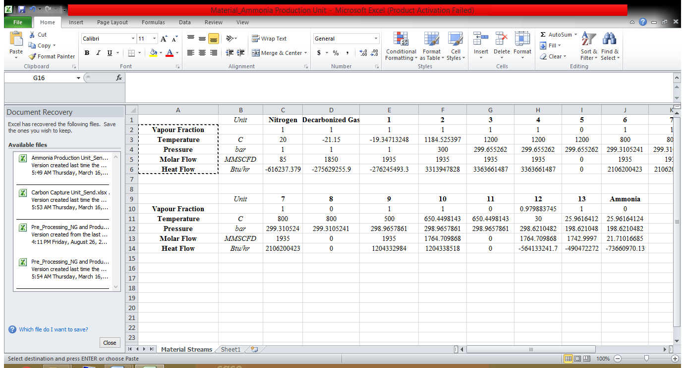
Figure A.1. Material streams at pre-processing and syngas production units with their operating conditions.
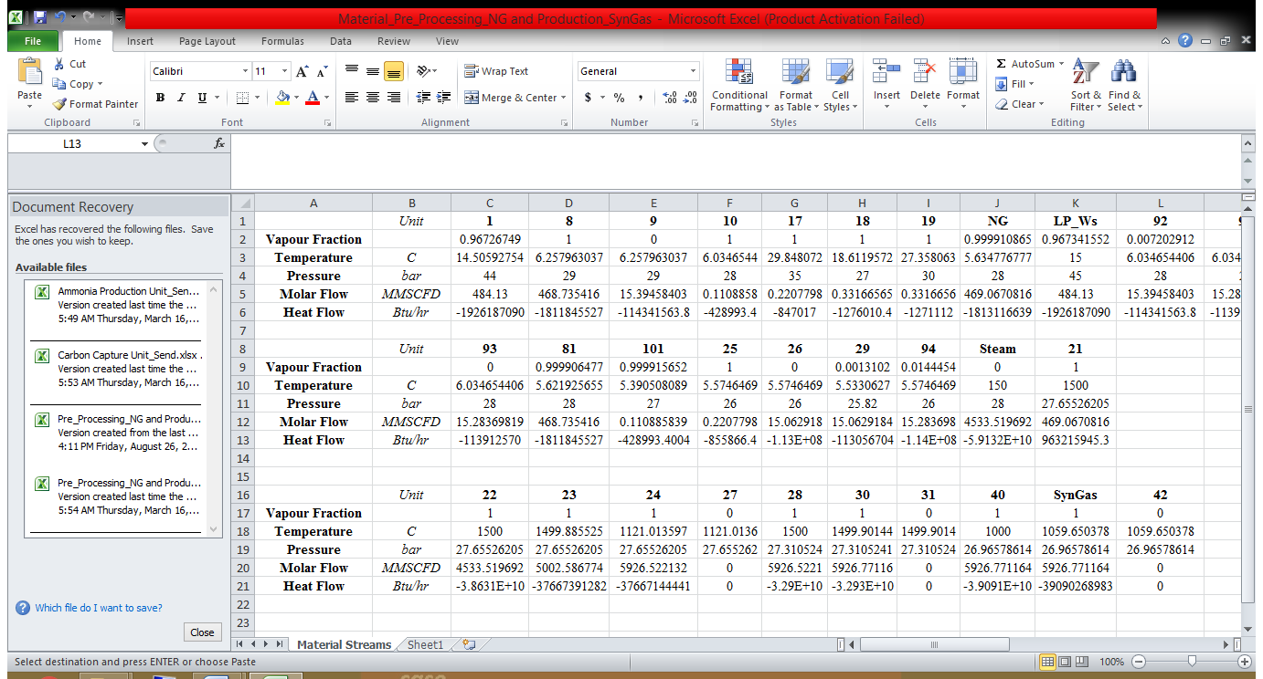
Figure A-2: Material streams at carbon capture units with their operating conditions
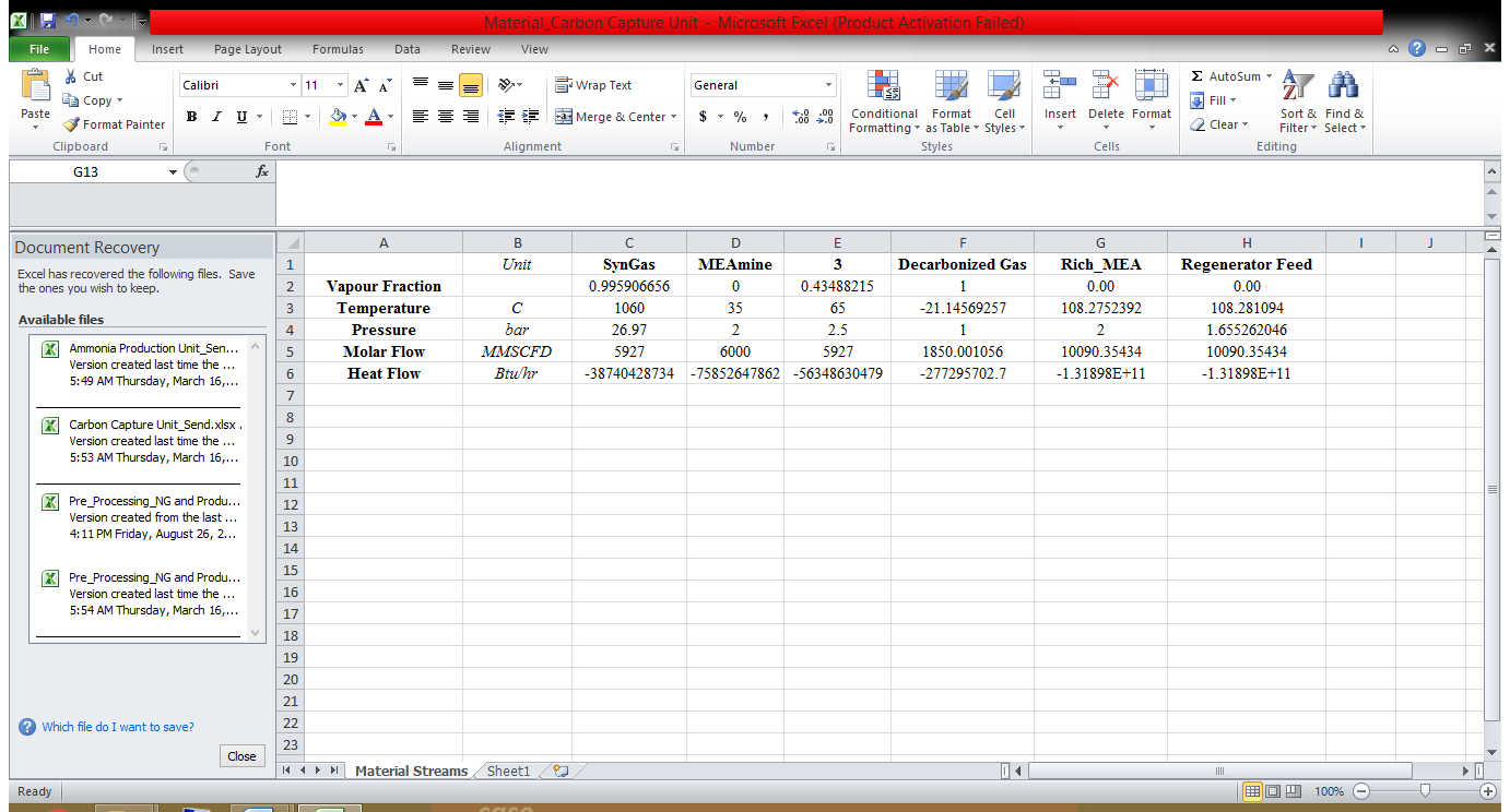
Figure A-3: Material streams at ammonia production units with their operating conditions