
Development of Heat Exchanger for Syngas Purification in a Smart Mini-Grid Gasification Power Plant
- Abe P.O.
- Titiladunayo I.F.
- 307-324
- Jul 8, 2024
- Mechanical Engineering
Development of Heat Exchanger for Syngas Purification in a Smart Mini-Grid Gasification Power Plant
Abe P.O.*, Titiladunayo I.F.
Department of Mechanical Engineering, The Federal University of Technology, Akure, Nigeria.
*Corresponding Author
DOI: https://doi.org/10.51584/IJRIAS.2024.906028
Received: 11 May 2024; Revised: 28 May 2024; Accepted: 01 June 2024; Published: 08 July 2024
ABSTRACT
The shell and tube heat exchanger was designed using a stainless pipe with a diameter of 203.2 mm (8 inches) and 3 mm thick. The design calculation results indicates that heat transfer rate was about and a tube length of 0.7 m was used and the number of tubes Nt is 17, this is required to cool the syngas from 350℃ to 80°C theoretically. Results obtained from CFD ANSYS software 2022 version showed that the verification of the model was achieved by comparing the theoretical temperatures of the syngas with the temperatures predicted from the simulation.
INTRODUCTION
Nigeria has been plagued for decades with the challenges of erratic energy availability and poor waste management. This has left majority of her citizens in total darkness, especially in the rural and urban arrears, while other citizens are faced with erratic and inconsistent electricity supply most of the time. Decentralization of electricity provision, using biomass, could help to address this challenge, particularly in rural and urban arrears (Akhator and Obanor, 2023). Biomass is a sustainable energy source obtained by combusting wood and other organic substances. Biomass is one of the most attractive renewable energy sources.
Gasification is a thermal process that converts carbonaceous substances into gaseous products by means of heat and a gasifying medium. Gasification normally occurs between 600℃ and 1000. Common gasifying agents include steam, air, carbon dioxide and hydrogen. This gas is referred to as either producer gas or syngas, based on its composition. Depending on several factors, composition and quantity of gas produced during the process of gasification, such as the kind of feedstock, the temperature at which the reaction occurs, the gasification medium used, and the design of the gasification reactor system. At low temperatures, the gasification product gas mainly comprises CO2, CO, H2, CH4, tar, N2, H2S and sundry other hydrocarbons (Ren et al., 2019). It then passes through more downstream processing to remove tar, CO2, and other undesirable products while increasing the levels of carbon monoxide and hydrogen. However, in the case of high-temperature gasification CO and H2 concentrations are already higher. The gaseous product resulting from gasification which is rich in carbon monoxide (CO) and hydrogen (H2) is usually referred to as syngas coupled with certain levels of impurities. It can be used either by combustion in engines for generating electricity or synthesis through Fischer-Tropsch process yielding liquid fuels and/or chemical feedstock. Methanation is the process that turns syngas into methane, often known as synthetic natural gas.
Fluidized bed gasifier provide a better quality of the product gas with low tar contents, since they are able to achieve so much higher mass and heat transfer rates compared to fixed beds. Additionally, a fluidized bed gasifier permits the use of catalysts throughout the gasification process. Ren et al., (2019) reported that industrial-scale entrained flow gasification reactors are more popular than others, because they work best within high-temperature range of 1300°C to 1500 °C and pressure range of and 25 bar to 30 bar respectively.
Syngas: Gasification of solid fuel results in the production of syngas, a composition formed from gas when high temperatures under pressure are applied to it. The primary constituents of the flammable gas consist of hydrogen and carbon monoxide. Gasification of solid biomass to produce syngas, a gaseous fuel, is the conversion process. Carbon monoxide (CO), hydrogen (H2), methane, carbon dioxide, and nitrogen make up the majority of syngas. In order to generate electricity and heat, internal combustion engines or gas turbines employ the syngas that is produced as a fuel gas (Ahrenfeldt et al., 2013).
A heat exchanger: An apparatus that facilitates the thermal energy transfer (enthalpy) of two or more fluids between a solid surface and a fluid for particles. When two fluids or solids that are at different temperatures come into direct thermal contact, this transfer takes place. A heat exchanger operates primarily without external heat or work interactions. Utilizing a heat exchanger, the syngas is cooled. The heat exchanger has demonstrated its ability to efficiently handle extremely dense tar particles and is specifically engineered to function under high pressure circumstances. These particles may cause the equipment to corrode, erode, or become clogged due to impaction deposition. One example of how this objective might be achieved is with a shell and tube heat exchanger (Howe et al., 2017). The goal of this paper is to design, model, and fabricate a shell-and-tube heat exchanger that might be used in a small-scale biomass gasification plant. The project’s mathematical analysis involves the application of numerical simulation to investigate the syngas’s cooling process and the tar’s subsequent separation from the syngas.
A shell and tube heat exchanger: has a tube bundle installed inside the shell. The fluid within the tube bundle can either be heated or cooled, while that passing across the tube bundles is also able to undergo heating and cooling. In most cases, a heat exchanger enables the transfer of heat between two fluids that can be either gas or liquid and have different initial temperatures. Heat is transferred from one fluid to another via the tube walls. The shell and tube bundle, a sheet, baffles, tie rods, spacers, and headers are among the parts of the heat exchanger (Chukwudi and Ogunedo, 2018). The upper header of the shell and tube heat exchanger allows the syngas to enter, where it travels via copper tubes inside the heat exchanger horizontally. A stainless-steel casing surrounds the tubes (Aldi et al., 2022). Water is the shell side fluid, which is fed from the bottom and directed by segmental baffles to flow over the tube bundle. These caged baffles feature a 33 percent reduction.
METHODOLOGY
A shell and tube heat exchanger is developed by this study for syngas cooling and purification. The heat exchanger consists of two major parts, which are the compartment of shell and the tube. The shell compartment is made of stainless steel cylinder of 8 inches (203.2 mm) diameter, 700 mm height and 3 mm in thickness and has corrosion resistance properties, while the tubes are made of copper pipes having high thermal conductivity which is necessary for energy transfer between the syngas and the cold water, 3/8 inches (9.525 mm) external diameter and 7.525 mm internal diameter and 700 mm long being carefully brazed to the tube sheet. The tube plate was made of stainless-steel plate of 5 mm thickness. Front end header and rear end header are made up of stainless-steel material of 5 mm thickness for the dished head.
Shell and tube heat exchangers are developed using Kern’s or Bell-Delaware method in most applications. However, Kern’s method is considered as the most commonly used method in preliminary design and provides conservative results; the Bell-Delaware method is more accurate, can provide detailed results and could predict the heat transfer coefficient with better accuracy (Abdulmumini et al., 2020). The shell and tube type heat exchanger to cool the syngas from 350℃ to 80℃ using water at the temperature of 10℃ with the application of Kern’s method. The heat exchanger is an assembly of one inlet and outlet chamber on the shell, seventeen (17) copper tubes with triangular pitch arrangement that allow the cooling syngas to flow through and the cold water to flow from shell side in opposite direction to that of the hot syngas as presented in figure 1 and figure 2.
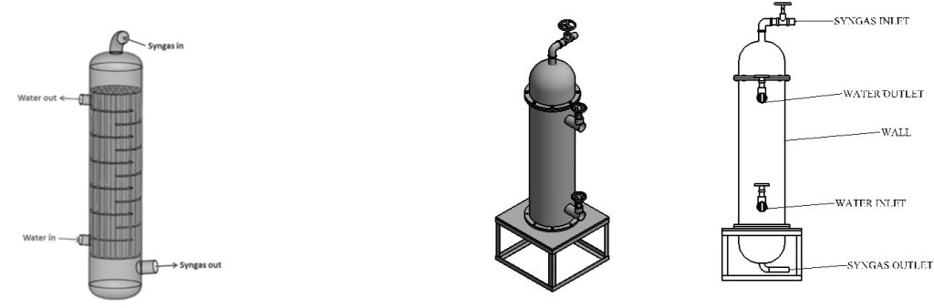
Figure 1a: Shell and tube heat exchanger for syngas cooling. Source: (Nicola Aldi et al., 2022) Figure 1b: Designed shell and tube heat exchanger
DESIGN PROCEDURE
The procedure adopted in the design of the shell and tube heat exchangers include: selection of the fluids to be placed on the tube side and shell sides respectively, selection of tube and shell materials based on physical properties of the two streams of fluid, selection of geometric parameters for the heat exchanger, specifying the flow rates and temperatures of the streams both at inlets and outlets, determination of the exchanger heat duty based on the parameter declared, estimation of the number of baffles to be used and its spacing, determination of both the tube and shell heat transfer coefficients and determination of the pressure drop on the tube and shell side of the exchanger.
Design Consideration
The shell and tube heat exchanger designed in this research is for syngas cooling and purification with inlet syngas temperature of 350℃ and flow rate of 0.1kg/s which will drop the temperature when cooled, from the reactor flowing into the tube, and exchanging heat with the cold water with assumed temperature of 10℃ passing through the shell. Minimum water mass flow rate of 0.3 kg/s was selected for the water and the water was expected to cool down the temperature of the syngas. At this temperature, the syngas would have cooled down satisfactorily while still in vapor state. Further cooling of the vapor is expected by a heat exchanger with ice to obtain the bio-fuel. This implies that two heat exchangers will be required for the general condensation process, but this research is limited to the first heat exchanger. The diameter of tube was selected based on Tubular Exchanger Manufacturing Association (TEMA) standards (TEMA, 1999), that standard tube outer diameter should be between 0.00635 m and 0.0508 m. According to (Thulukkanam, 2013), small tube diameters produces high heat transfer coefficient and are suitable for applications where effective heat transfer is desired. Hence in this research, the inner diameter of tube selected was 0.007525 m with an outer diameter of 0.009525 m, and the selected number of tube and baffle thickness are 17 numbers and 0.005 m respectively. Prototype heat exchanger was designed for the cooling of the syngas. The baffle thickness was selected as recommended by TEMA standards
Factors considered when designing Shell and Tube Heat Exchanger
a) Heat Balance of Shell and Tube Heat exchanger
The thermal design was done using the Bell Delaware method as suggested by Abdulmumini et al. 2020. Numerous parameters were considered in the analysis such as the shell side heat transfer coefficient (\(h_i\)), total heat transfer coefficient (\(h_T\)), log mean temperature difference (\(\Delta T_m\)), Syngas inlet temperature (\(T_{h_i}\)), and tube transfer coefficient (\(h_t\)). The overall heat transfer coefficient is determined by the combined effects of fouling resistances, heat transfer coefficients, and surface efficiency of the tubes.
The overall energy balance was determined using equations (3.1) and (3.2).
\[Q = m_h C_p (T_{h_i} – T_{h_o}) = m_c C_p (T_{c_o} – T_{c_i}) \tag{1}\]
\[Q = U A F \Delta T_{lm} \tag{2}\]
Where:
- \(Q\) is Heat duty
- \(m_c\) is Mass flow rate of cold water
- \(C_p\) is Specific heat capacity of water
- \(T_{c_o}\) is Outlet temperature of cold water
- \(T_{c_i}\) is Inlet temperature of cold water
- \(m_h\) is Mass flow rate of hot syngas
- \(T_{h_o}\) is Outlet temperature of hot syngas
- \(T_{h_i}\) is Inlet temperature of hot syngas
- \(U\) is Overall heat transfer coefficient
- \(A\) is Heat exchanger surface area
- \(\Delta T_{lm}\) is the log mean temperature difference
- \(F\) is Corrosion factor
Assuming only sensible heat is transferred and then the heat balance for the hot fluid is given by:
\( Q_h = m_h C_P (T_{h,i} – T_{h,o}) \)
The inlet temperature of the syngas (\(T_{h,i}\)) is taken to be 350°C while its exit temperature (\(T_{h,o}\)) from the heat exchanger remains at 80°C.
Therefore:
\[Q_h = Q_c = \dot{m}_h C_p (T_{h,i} – T_{h,o}) = \dot{m}_c C_p (T_{c,o} – T_{c,i})\]
\[T_{c,o} – T_{c,i} = \frac{\dot{m}_h C_p (T_{h,i} – T_{h,o})}{\dot{m}_c C_p}\]
\[T_{c,o} = T_{c,i} + \frac{\dot{m}_h C_p (T_{h,i} – T_{h,o})}{\dot{m}_c C_p}\]
\(T_{c,i} = 10°C\)
\(T_{c,o} = unknown\)
\(m_{cw} = 0.3 \, \text{kg/s}\)
\(m_{hg} = 0.10 \, \text{kg/s}\)
\(C_{Pw} \, \text{for water} = 4.197 \times 10^3 \, \text{J/kg.K}\)
\(T_{h,i} = 350°C\)
\(T_{h,o} = 80°C\)
\(C_{Pg} \, \text{for syngas} = 1.142 \times 10^3 \, \text{J/kg.K}\)
Therefore:
\[T_{c,o} = 24.5 + 10 = 34.5°C\]
This means the exit temperature is expected to be 34.5°C which implies that the temperature of the cold water is increased from 10°C to 34.5°C.
Then the Heat Duty for Hot fluid is given by:
\[Q_h = \dot{m}_h C_p (T_{h,i} – T_{h,o})\]
\[Q_h = 0.1 \times 1.142 \times 10^3 (350 – 80) = 30834 \, \text{W} = 30.834 \, \text{kW}\]
Also the Heat Duty for Cold fluid is given by:
\[Q_c = \dot{m}_c C_p (T_{c,o} – T_{c,i})\]
\[Q_c = 0.3 \times 4.197 \times 10^3 (34.5 – 10) = 30848 \, \text{W} = 30.85 \, \text{kW}\]
b) Tube Pressure Drop
When designing a heat exchanger, it is crucial to take into account the pressure drop. A common design limitation could be expressed as \(\Delta P \leq N \, \text{psi}\) where the value of \(N\) is given.
\( f_{\text{corrected}} \left( \frac{L}{D} \right) \left( \frac{1}{2} P V_m^2 \right) \tag{3}\)
To this, we add:
\[\Delta P_r = 4 \times \text{Number of tubes} \times \frac{G_t^2}{2P} \tag{4}\]
\[G_t = PV is the mass velocity and is defined \]
\[G_t = \frac{\text{Mass flow rate}}{\text{Total flow area available per pass}}\]
f = Friction factor is given by:
\[ \frac{1}{\sqrt{f}} = -2.0 \log \left( \frac{\epsilon/D}{3.7} \right) + \frac{2.51}{R_{e\sqrt{f}}} \tag{5}\]
\[ \Delta P = f_{\text{corrected}} \frac{L}{D} \left( \frac{1}{2} \rho V_m^2 \right) + \Delta P_r \]
\[= f_{\text{corrected}} \frac{L D}{12} \rho V_m^2 + 4 N P \frac{G_t^2}{2 \rho} \tag{6}\]
\[\text{Re} = \frac{d_i V_{\max} \rho}{\mu} \tag{7}\]
c) Shell Side Pressure Drop
The calculation of the pressure drop on the shell-side is determined using:
\[ \Delta P_{\text{shell}} = \frac{2f \cdot G_S^2 \cdot D_S \cdot (N_B + 1)}{\rho \cdot D_e \cdot \left( \frac{\mu}{\mu_S} \right)^{0.14} } \tag{8}\]
In this equation, \(f\) is a fanning friction factor for flow on the shell side, \(G_S\) is the mass velocity on the shell side, \(D_S\) is the inside diameter of baffles, \(\rho\) is the density of the shell side fluid, and \(D_e\) is an equivalent diameter.
The mass velocity \(G_S = \frac{m}{S_m}\) where \(m\) is the mass flow rate of the fluid and \(S_m\) is the cross flow area measured close to the central symmetry plan of the shell containing its axis (Ramesh 2003).
This is defined as:
\[\text{Cross flow area} = \frac{D_s L_B \times \text{Clearance}}{\text{Pitch}} \tag{9}\]
Where \(L_B\) is the baffle spacing, and the clearance and pitch are defined in the coefficient of heat transfer below:
The equivalent diameter (\(D_e\)) is given as: \(D_e = \frac{4 C P S_n^2 – \pi d_0}{2 \pi d_0} \tag{10}\)
Here \(d_0\) is the outside diameter of the tube and \(s_n\) is the pitch (centre to centre distance) of the tube assembly. The constant \(C_P = 1\) for a square pitch and \(C_P = 0.87\) for a triangular pitch. The Reynolds number (\(Re\)) is defined as:
\[Re= \frac{D_e G_s}{\mu} \tag{11}\]
Where \(\mu\) is the viscosity of the shell side fluid?
\[f=\exp (0.576-0.29\ln(Re)) \tag{12}\]
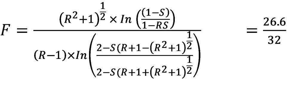
d) Mean Temperature Difference
The temperature gradient acts as the stimulus for heat transfer. A true countercurrent flow occurs when two streams move in opposite directions on the surface of a tube wall. As a result, the outlet temperature of both streams may differ due to changes in \(\Delta T\) along the heat exchanger length. The temperature difference for a single location should be considered to figure out the average value of heat transfer area. This value calculated using the weights is indicated as LMTD. The term concurrent flow refers to a situation where hot and cold streams move in the same direction.
\[Q=UA F \Delta T_{lm} \tag{13}\]
But \(\Delta T_{lm}=F \Delta T_{lm} \tag{14}\)
\[\Delta T_{lm}= \frac{(T_{hi}- T_{co}) – (T_{ho}- T_{ci})}{\ln \left( \frac{T_{hi}- T_{co}}{T_{ho}- T_{ci}} \right)} \tag{15}\]
The log mean temperature difference as defined in the equation is given by:
\[\Delta T_{lm}= \frac{(T_{hi}- T_{co}) – (T_{ho}- T_{ci})}{\ln \left( \frac{T_{hi}- T_{co}}{T_{ho}- T_{ci}} \right)}\]
Hence
\[LMTD= \frac{(T_{hi}- T_{co}) – (T_{ho}- T_{ci})}{\ln \left( \frac{T_{hi}- T_{co}}{T_{ho}- T_{ci}} \right)}\]
\[LMTD= \frac{350-34.5-80-10}{\ln \left( \frac{350-34.5}{80-10} \right)} = \frac{315.5-70}{\ln \left( \frac{315.5}{70} \right)}= \frac{245.5}{\ln(4.5)}\]
\[= \frac{245.5}{1.51}= 162.6^\circ C\]
This value is the equivalent average temperature difference between the hot syngas and the cold water.
e) Fouling
A fouled surface is normally considered to be one that presents some additional heat transfer resistance due to the buildup of foreign materials or scale. This additional thermal resistance will naturally cause the heat transfer to be less than in the case of no fouling resistance; the prediction of scale buildup or the corresponding effect on heat transfer is a most difficult task. The actual performance of a heat exchanger can be evaluated after some periods of service and the fouling resistance determined (Çengel 1997).
For a clean surface:

\[U_f= \frac{1}{\frac{1}{h_0}+ R_0+ \frac{A_0 \ln(r_0/r_i)}{R_i}+ \frac{A_0}{A_i h_i}} \tag{18}\]
\[U_0= \frac{1}{\frac{1}{h_0}+ \frac{A_0 \ln(r_0/r_i)}{2 \pi K} + \frac{A_0}{A_i h_i}} \tag{19}\]
\[ \frac{1}{U_A} =\frac{1}{U_i A_i}= \frac{1}{U_0 A_0} \tag{20}\]
where \(A_i=\pi d_i L\) and \(A_0=\pi d_0 L\).
Total resistance \(R\):
\[R= \frac{1}{U_A} =\frac{1}{U_i A_i}= \frac{1}{U_0 A_0}= \frac{1}{h_i A_i}= R_{wall}+ \frac{1}{h_0 A_0} \tag{21}\]
\[R= \frac{1}{h_i A_i}+ \frac{\ln(d_0/d_i)}{2 \pi K L}+ \frac{1}{h_0 A_0} \tag{22}\]
f) Correction Factor
The use of a correction factor (F) is necessary when calculating the log mean temperature difference for a counter current heat exchanger. This is because the flow of the streams in counter current flow is more intricate compared to concurrent flow.
The adjustment factor is dependent on the parameters \(P\) and \(R\) (Shah and Skiepko 2005).
\[P= \frac{t_2-t_1}{T_1-t_1} \quad \text{and} \quad R= \frac{T_1-T_2}{t_2-t_1} \tag{23}\]
As stated in the equation, the correction factor \(F\) is a function of \(S\) and \(R\).
\[S= \frac{t_2-t_1}{T_1-t_1} = \text{range of tube fluid maximum temperature difference}\]
\[R= \frac{T_1-T_2}{t_2-t_1}= \text{range of shell fluid range of tube fluid}\]
The temperature of cold fluid increased from \(10^\circ C\) to \(34.5^\circ C\) and that of hot syngas decreased from \(350^\circ C\) to \(80^\circ C\). Thus;
Capacity Ratio
\[R=\frac{T_{h,i}-T_{h,o}}{T_{c,0}-T_{c,i}}=1.02\]
Effectiveness
\[S=\frac{T_{c,0} – T_{c,i}}{T_{h,i} – T_{c,i}}=0.09\]
Correction Factor
=0.8281=83%
The value of \(F\) shows the extent to which the flow approximates to counter-current nature.
\[F = 1\] means the flow is purely counter-current. Hence the value shows 83% approximation to counter current flow.

Where \(A=\frac{1}{P-1-R}=1.11m^2\).
Corrected (LMTD)
Corrected LMTD=\(F\times LMTD\)
Corrected ( LMTD)=0.83×162.6=1350 C
Overall Heat Transfer Coefficient (For Hot fluid)
\[U_{Design}=\frac{Q_h}{A\times Corrected LMTD} \tag{25}\]
Where; A= (1/S)- 1-R=(1/0.09)- 1-11 =1.11m2,
g) Determination of the Heat Exchanger Surface Area
The area was calculated to be \(0.351m^2\) using the equation. The value of \(U_0\) is assumed to be 650 W/m\(^2\) \(^\circ C\). That is the overall heat transfer coefficient of water to gasoline \(F = 0.90\) and \(\Delta T_{lm} = 162.6^\circ C\). \(A\) represents the whole surface area that is in contact with the fluid whether it is at a high or low temperature.
\[A_0=\frac{Q}{U_0\Delta T_m}=\frac{Q}{U_0F\Delta T_{lm}} \tag{26}\]
Where: \(A_0\) is outside tube surface area \(Q\) is heat duty – heat exchanger between tube and shell side fluid \(U_0\) is overall heat transfer coefficient \(F\) is correction factor \(T_m\) is True mean temperature \(T_m = F\Delta T_{lm}\) \(T_{lm}\) is log mean temperature difference.
h) Total Number of Tubes
The number of tubes \(N_t\) as described by Holman 2002 was 17 tubes. Since the number of tubes is very small as well as the diameter this will reduce the pressure drop and the shell diameter.
\[N_t=\frac{A_0}{\pi d_0 L} \tag{27}\]
Where \(A_0\) is outside tube surface area \(d_0\) is outside tube diameter \(L\) is Tube length \(N_t\) is number of tubes.
i) Tube Layout and Tube Sheet Thickness
The tube ratio is given by:
\[\frac{P_T }{d_0} = 1.25 \quad > \quad P_T=1.25d_0 \tag{28}\]
Where \(P_T\) is Tube pitch \(d_0\) is Tube outside diameter.
Tube sheet thickness is given by:
\[L_{ts} = 0.1D_s \tag{29}\]
Where \(L_{ts}\) is Tube sheet thickness \(D_s\) is Shell internal diameter (Holman 2002).
j) Number of Baffles, Baffle Cut and Baffle Spacing
The number of baffle (\(B\)) is given by:
\[N_b=\frac{L_{ti}}{B} \tag{30}\]
Where \(L_{ti}\) is Length of the tube and \(B\) is baffle spacing.
Baffle spacing (\(B\)) is given by:
\[B= \frac{60}{100} \times D_s \tag{31}\]
Where \(D_s\) is Shell internal diameter.
Segmental baffle cut as a percent of \(D_s\) is given by:
\[B_c=\frac{L_{bch}}{D_s} \times 100\% = \frac{B}{D_s} \tag{32}\]
Where \(L_{bch}\) is segmental baffle cut length \(B\) is Baffle spacing (J.P Holman 2002).
k) Determination of Tube Side Heat Transfer Coefficient
The Reynolds number Prandtl number and tube diameter all affect the heat transfer coefficient on the inner surface of the tube. The heat transfer coefficient is most significantly influenced by the liquid viscosity which varies significantly (Ramesh 2003).
The equation governing turbulent heat transport inside a tube is:
\[Nu=0.023 (Re)^{0.8}(Pr)^{0.4} \tag{33}\]
\[Nu= \frac{h_i d_i}{K}\quad Re= \frac{dV_{max}\rho}{\mu}\quad \text{and} \quad Pr= \frac{C_P \mu}{K}\]
For the inner surface of the tube:

l) Determination of Shell Side Heat Transfer Coefficient
When baffles are present in a tube bundle and the flow around the tubes is unobstructed the heat transfer coefficient is higher than it would be in the absence of baffles. When baffles are present the heat transfer coefficient outside the tube bundle is referred to as the “shell-side heat transfer coefficient”. As a result, the shell side heat transfer coefficient can be written as:
\[Nu= \frac{h_0 d_h}{K}=0.023 (Re)^{0.8}(Pr)^{0.4}\]
![]()
\[Re= \frac{d_h V_m \rho}{\mu} tag{36}\]
Where; \(Nu\) is Nusselt number \(Pr\) is Prandtl number \(h_0\) is Heat transfer coefficient for outer surface of the tube \(d_h\) is Hydraulic diameter \(V_m\) is Mean velocity of the fluid through shell \(\rho\) is density of the fluid \(\mu\) is Dynamic viscosity of shell side fluid \(C_p\) is Specific heat capacity of the fluid \(Re\) is Reynolds number \(K\) is Thermal conductivity of the shell fluid (Ramesh 2003).
m) Determination of Overall Heat Transfer Coefficient
The rate of heat transfer between the two fluids can then be expressed as:
\[Q= \frac{\Delta T}{R}=UA\Delta T= U_i A_i \Delta T=U_0 A_0 \Delta T tag{37}\]
Where; \(U\) is the overall heat transfer coefficient whose unit is W/(m2 0C ).
The fluids to be used are expected to some extent fouling; hence fouling effects have to be considered (Çengel 2003). Thus for these surfaces:
![]()
Where;
\[U_f\] is Overall heat transfer coefficient \(h_i\) \(h_0\) is Heat transfer coefficient for inside and outside tube \(A_i\) \(A_0\) is Inner and outer surface area of the tube \(h_i\) \(h_0\) is outer and inner radius of the tube \(R_o\) \(R_i\) is Outer and inner fouling resistance.
RESULTS AND DISCUSSION
The syngas enters the heat exchanger at a temperature of 350 oC (623K), and a mass flow rate of 0.1 kg/s, while the cold water at 10 enters the heat exchanger in a counterflow direction with a flow velocity of 0.3 m/s. The temperature of the syngas is therefore reduced below the condensation temperature of tar, moisture and pyroligneous liquid as it looses heat to the circulating water on its passage through the exchanger. Consequently, all exstraneous content (impurities) of the syngas is separated from it by the process condensation. The heat exchanger is designed to receive syngas for purification at 350℃ ≤Ti≤ 150℃ and dischage purified syngas at 87℃ ≤To≤ 80℃.
Simulation parameters and boundary conditions
The parameters and boundary conditions applied in this simulation are summarized as follows;
Table 1: Simulation parameters and boundary conditions
| S/N | PARAMETER NAME | NUMERICAL VALUE | UNITS |
| 1 | Water inlet temperature | 10 | |
| 2 | Water outlet temperature | 34.5 | |
| 3 | Syngas inlet temperature | 350 | |
| 4 | Assummed syngas temperature | 80 | |
| 5 | Water inlet velocity | 0.3 | m/s |
| 6 | Syngas mass flow rate at inlet | 0.1 | kg/s |
| 7 | Acceleration due to gravity | 9.8 | m/s2 |
| 8 | Diameter of shell | 203.2 | mm |
| 9 | Shell thickness | 5 | mm |
| 10 | Tube thickness | 1 | mm |
| 11 | Number of tubes | 17 | Nos |
| 12 | Tube length | 700 | mm |
| 13 | Outside Tube Diameter | 9.525 | mm |
| 14 | Inside tube diameter | 7.525 | mm |
| 15 | Thickness of dished head | 5 | mm |
| 16 | Baffle spacing | 122 | mm |
| 17 | Number of baffle | 5 | Nos |
| 18 | LMTD | ||
| 19 | Corrected LMTD | ||
| 20 | Heat duty for hot fluid | 30.83 | kW |
| 21 | Heat duty for cold fluid | 30.848 | kW |
| 22 | Overall heat transfer coefficient (tube) | ||
| PROPERTIES OF WATER | |||
| 23 | Water density | 997.1 | kg/m3 |
| 24 | Specific Heat Capacity cp | 4186 | J/kgK |
| 25 | Viscosity | 3.55 10-5 | Pa-s |
| 26 | Thermal Conductivity | 0.670 | W/m-K |
| PROPERTIES OF SYNGAS | |||
| 27 | Density | 0.963 | kg/m3 |
| 28 | Specific Heat Capacity cp | 1142 | J/kgK |
| 29 | Viscosity | 1.655 10-5 | Pa-s |
| 20 | Thermal Conductivity | 0.058 | W/m-K |
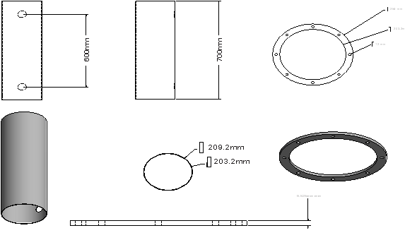
Figure 3: Autocad design of Shell
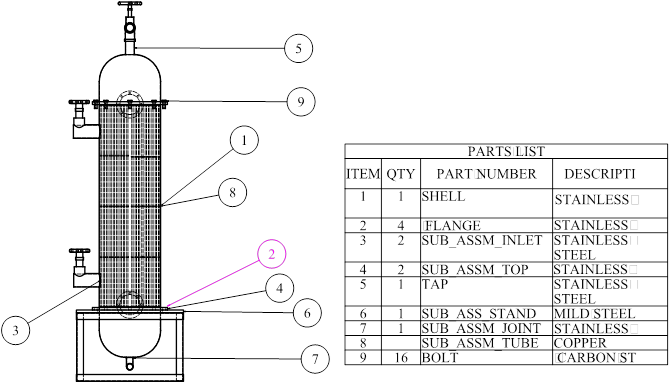
Figure 4: Sectional view of shell and tube heat exchanger
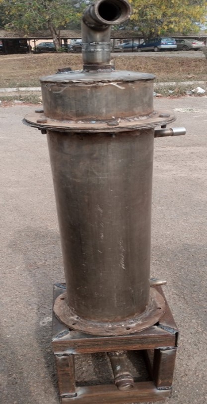
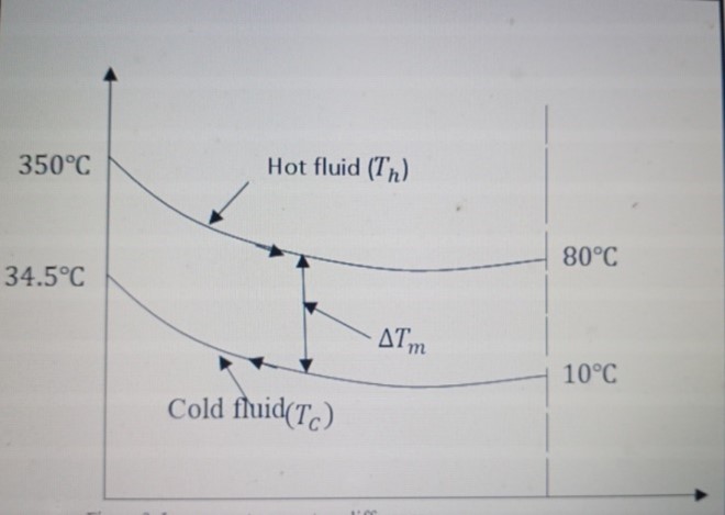
Plate 1: Front view of the fabricated shell and tube heat exchanger
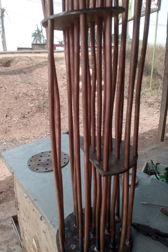
Plate 2: Construction process of the tubes on the tube plate and baffle
SIMULATION RESULT
After successful meshing of the models, ANSYS-FLUENT environment was launched and the meshed models were solved 500 iterations were selected for the solution, and the solution was stopped at 450th iterations. This is because the residual plots maintained uniform line at 300th iterations to 500th iterations. In addition, it indicates that the obtained results have a negligible difference within these iterations and any further iteration will result to increase in computation time which will equally increase the computation cost. In order to further corroborate the convergence of the solution, the convergence history of the static temperature of the tube outlet with respect to time was also checked. In this case, the solution was allowed to continue to 500th iteration. Furthermore, area weighted average static temperature was computed and displayed at the FLUENT console for the seventeen tube outlets and the net temperature was 360K (87℃) as in figure 8. Similar to the convergence plot of static temperature of tube fluid (syngas), the outlet static temperature of shell fluid (water) was also observed and can be seen in figure 7 and the net temperature that was displayed at the FLUENT console for the shell outlet was 303K (30℃). By comparing the theoretical temperature with the temperature predicted by the simulation, the model was verified. the percentage difference between the results of the simulation and the theory. These results are presented in Table 2 and the estimated percentage deviations for the tube side and the shell side are 8.75% and13.04% respectively. While the deviation in the fouling factor may be caused by uneven velocity profiles, backflows, and eddies generated on the shell side of a segmentally-baffled heat exchanger, the deviation in the heat transfer surface can be attributed to changes in temperature difference, physiochemical properties of the fluids, geometry of the heat exchanger, and velocity of the flowing fluids.
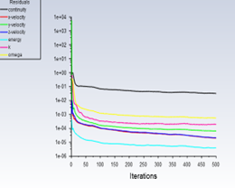
Figure 5 Simulation Progress graph
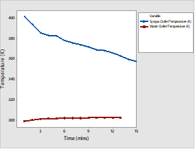
Figure 6 Graph showing comparison between Syngas and Water Outlet Temperature
Figure 5 shows that the simulation was done in 500 iterations. Figure 6 shows that while the temperature of water increases (increased to 303K (30)) slightly it causes a significant decrease in the temperature of the syngas (reduced to as low as 360K (87)). This implies that the thermal efficiency of the designed heat exchanger is sufficient and acceptable for industrial applications.
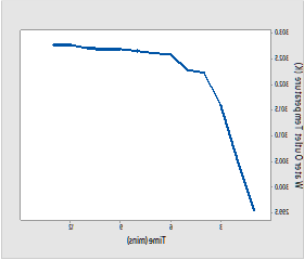
Figure 7 Variation of Water Outlet Temperature with time
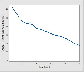
Figure 8 Variation of Syngas Outlet Temperature with time
Figure 7 shows that the temperature of water at its outlet increases from 299K (260C) to 303K (300C) within 15 minutes, while figure 8 shows that the temperature of syngas at its outlet decreases from 400K (1270C) to 360K (870C) within 15 minutes
CONCLUSION
In this research, the development of shell and tube heat exchanger for syngas cooling to a much lower temperature was carried out. Design procedures and consideration as recommended by literatures was carefully adopted. The designed heat exchanger was evaluated to perform numerical simulation using computational fluid dynamics (CFD) tools. Results from the theoretical and CFD simulation shows that the heat exchanger is efficiently designed to reduce the temperature of the syngas below 90 provided the designed input parameters are obtained. The shell and tube heat exchanger prototype was developed and the parameters such as heat duty, capacity ratio, effectiveness, overall heat transfer coefficient were determined.
REFERENCES
- Ahrenfeldt, J., Thomsen, T. P., Henriksen, U., & Clausen, L. R. (2013). Biomass gasification cogeneration – A review of state of the art technology and near future perspectives. Applied Thermal Engineering, 50(2), 1407–1417. https://doi.org/10.1016/j.applthermaleng.2011.12.040
- Akhator, P., & Obanor, A. I. (2023). Development of Mechanical Purification System for Synthesis. Journal of Engineering for Development, 15(3), 1–17.
- Aldi, N., Casari, N., Pinelli, M., Suman, A., & Vulpio, A. (2022). Performance Degradation of a Shell-and-Tube Heat Exchanger Due to Tar Deposition. Energies, 15(4). https://doi.org/10.3390/en15041490
- Anis, S., & Zainal, Z. A. (2011). Tar reduction in biomass producer gas via mechanical, catalytic and thermal methods: A review. Renewable and Sustainable Energy Reviews, 15(5), 2355–2377. https://ideas.repec.org/a/eee/rensus/v15y2011i5p2355-2377.html
- Bashiru Abdulmumuni, Adedeji Mathew Ayoade, Ologunye Opeyemi Buhari, Azeez Rasheed Olatunde, Fanifosi Johnson Olaniyi. “Design, Fabrication and Performance Evaluation of a Shell and Tube Heat Exchanger for Practical Application” , European Journal of Engineering Research and Science, 2020 5(8) 835-845
- Bosmans, A., Wasan, S., & Helsen, L. (2013). Waste to Clean Syngas: Avoiding Tar Problems. 2nd International Enhanced Landfill Mining Symposium | Houthalen-Helchteren, 1–21. https://doi.org/10.5772/54528
- Bowman, R. A., Vigil, M. F., Nielsen, D. C., & Anderson, R. L. (1999). Soil Organic Matter Changes in Intensively Cropped Dryland Systems. Soil Science Society of America Journal, 63(1), 186–191. https://doi.org/10.2136/SSSAJ1999.03615995006300010026X
- Çengel, Y. A. (1997). Introduction to thermodynamics and heat transfer. 922.
- Chukwudi, B. C., & Ogunedo, M. B. (2018). Design and Construction of a Shell and Tube Heat Exchanger. Elixir International Journal, 118(May), 50687–50691. www.elixirpublishers.com
- Devi, L., Ptasinski, K. J., & Janssen, F. J. J. G. (2003). A review of the primary measures for tar elimination in biomass gasification processes. Biomass and Bioenergy, 24(2), 125–140. https://doi.org/10.1016/S0961-9534(02)00102-2
- Dewanto, M. A. R., Januartrika, A. A., Dewajani, H., & Budiman, A. (2017). Catalytic and thermal cracking processes of waste cooking oil for bio-gasoline synthesis. AIP Conference Proceedings, 1823(June). https://doi.org/10.1063/1.4978172
- Howe, D. T., Taasevigen, D., Garcia-Perez, M., McDonald, A. G., Li, G., & Wolcott, M. (2017). Steam gasification of a thermally pretreated high lignin corn stover simultaneous saccharification and fermentation digester residue. Energy, 119, 400–407. https://doi.org/10.1016/j.energy.2016.12.094
- JieRen, Jing-Pei Cao, Xiao-Yan Zhao, Fei-Long Yang, Xian-Yong Wei (2019) Recent advances in syngas production from biomass catalytic gasification: A critical review on reactors, catalysts, catalytic mechanisms and mathematical models,
- Renewable and Sustainable Energy Reviews, Volume 116, 109426, ISSN 1364-0321,
- https://doi.org/10.1016/j.rser.2019.109426.
- (https://www.sciencedirect.com/science/article/pii/S1364032119306343)
- Kabeyi, M. J. B., & Olanrewaju, O. A. (2022). Biogas Production and Applications in the Sustainable Energy Transition. Journal of Energy, 1–43. https://doi.org/10.1155/2022/8750221
- Kallalu Harika et al., (2017) Fabrication of Shell and Tube Heat Exchanger using Helical Baffles based on Kern’s Principle. International Journal of Current Engineering and Technology Vol.7, No.3, 821-826
- Lawal, D. A. (1990). A review of: “ HEAT EXCHANGER DESIGN ” 2nd Edition Arthur P. Fraas John Wiley and Sons, New York 1989, 547 pages . Drying Technology, 8(2), 431–432. https://doi.org/10.1080/07373939008959893
- Mastellone, M. L., & Arena, U. (2008). Olivine as a Tar Removal Catalyst During Fluidized Bed Gasification of Plastic Waste. American Institute of Chemical Engineers, 54(6), 1656–1667.
- Meha, D., Avdiu, A., Krasniqi, F., Muriqi, A., Berisha, X., Meha, D., Avdiu, A., Krasniqi, F., Muriqi, A., & Berisha, X. (2017). Experimental Analysis of Performance of Heat Exchanger with Plate Fins and Parallel Flow of Working Fluids. World Journal of Engineering and Technology, 5(3), 435–444. https://doi.org/10.4236/WJET.2017.53038
- Molino, A., Larocca, V., Chianese, S., & Musmarra, D. (2018). Biofuels production by biomass gasification: A review. Energies, 11(4), 1–31. https://doi.org/10.3390/en11040811
- Musilim, A.A.,Nwagwo, A. and Uche, O. K. (2017): Effect of baffle cut sizes on temperature and pressure drop at various mass flow rate in a shell and tube heat exchanger. International Journal of Engineering, Science and Mathematics. Vol.6, Issue 1,pp.1-10.
- Ramesh K. Shah and Dusˇan P. Sekulic (2003). Fundamentals of heat exchanger design. ISBN 0-471-32171-0 1.
- Shah, R. K. and Skiepko, T. (2005). Exchanger Performance Behavior Through Irreversibility Analysis for 1-2 TEMA G HeatExchangers. Journal of Heat Transfer, 127(12), 1296–1304. https://doi.org/10.1115/1.2098827
- Shukla, A. (n.d.). Economic Heat Exchanger Is ? | Global Journals of Research in Engineering. Retrieved December 31, 2023, from https://engineeringresearch.org/index.php/GJRE/article/view/1426/2-Economicheat-Exchanger-Is_JATS_NLM_xml
- Steynberg, A. P., & Nel, H. G. (2004). Clean coal conversion options using Fischer-Tropsch technology. Fuel, 83(6), 765–770. https://doi.org/10.1016/j.fuel.2003.09.023
- Thapa, S., Bhoi, P. R., Kumar, A., & Huhnke, R. L. (2017). Effects of syngas cooling and biomass filter medium on tar removal. Energies, 10(3), 1–12. https://doi.org/10.3390/en10030349
- Thapa, S., Indrawan, N., Bhoi, P. R., Kumar, A., & Huhnke, R. L. (2019). Tar reduction in biomass syngas using heat exchanger and vegetable oil bubbler. Elsevier, 1–25. https://www.sciencedirect.com/science/article/pii/S0360544219304499
- Types of Biomass Fuels | Hurst Boiler, Inc. (n.d.). Retrieved December 31, 2023, from https://www.hurstboiler.com/biomass_boiler_systems/biomass_fuel_types
- Upadhyay, H., Vashisht, U., Dhall, A., Diwakar, P., & Juneja, J. (2019). A review on heat exchanger. International Journal Of Applied Research In Science And Engineering, 3(3), 35–38. https://doi.org/10.5958/2278-4853.2021.01073.9
- Verhoeven, L. M. (2011). Radical tar removal : numerical modeling of tar conversion in a partial combustion reactor (Vol. 1, Issue 2011). https://doi.org/10.6100/IR719415
- Vukic,M.C., Tomic, M. A., Zivkovic, P. M. and Ilic, G. S. (2013): Effect of Segmental Baffles on the Shell and Tube Heat Exchanger Effectiveness. Scientific Paper, Hem. Ind. Vol. 68 Issue 2, pp.171-177.
- What is biomass, types, methods of converting biomass to energy, its advantages and disadvantages. (n.d.). Natural Energy Hub. Retrieved December 31, 2023, from https://naturalenergyhub.com/renewable-energy/biomass-types-methods-converting-energy-advantages-disadvantages/
- Woolcock, P. J. (2013). Development and application of a rapid sampling technique for identification and quantification of compounds in high temperature process gas streams produced from biomass gasification and pyrolysis. 1–229.
- Zena K. K., Kassimmuna S., Adel, H. and Abdul, Y. (2016): “CFD study for cross flow heat exchanger with integral finned tube”, International Journal of Scientific and Research Publication, Volume 6, Issue 6, pp.668-677.
- Zhao, Z., Lakshminarayanan, N., Swartz, S. L., Arkenberg, G. B., Felix, L. G., Slimane, R. B., Choi, C. C., & Ozkan, U. S. (2015). Characterization of olivine-supported nickel silicate as potential catalysts for tar removal from biomass gasification. Applied Catalysis A: General, 489, 42–50. https://doi.org/10.1016/j.apcata.2014.10.011