
Sensitivity Analysis of Biomass Gasification Reactors Using Aspen Plus
- Jaja Zina
- Gwarah Bright Gogoro
- 117-130
- Mar 4, 2025
- Education
Sensitivity Analysis of Biomass Gasification Reactors Using Aspen Plus
1Jaja Zina, 2Gwarah Bright Gogoro
1Rivers State University, Faculty of Engineering, Department of Chemical/Petrochemical Engineering, Port Harcourt, Rivers State, Nigeria
2Kenule Beeson Saro-Wiwa Polytechnic, Bori, School of Engineering, Department of Chemical Engineering, Port Harcourt, Rivers State, Nigeria
DOI: https://doi.org/10.51584/IJRIAS.2025.10020010
Received: 17 January 2025; Accepted: 24 January 2025; Published: 04 March 2025
ABSTRACT
Municipal solid waste (MSW) management has become a critical issue in rapidly growing urban centers like Port Harcourt, Nigeria, due to increasing waste generation from population growth and industrial activities. Traditional waste disposal methods, such as landfilling and open burning, present significant environmental challenges, including greenhouse gas emissions, land degradation, and air pollution. Gasification, a thermal conversion technology, offers a sustainable waste-to-energy solution by transforming MSW into syngas (a mixture of hydrogen, carbon monoxide, methane, and other gases), which can be utilized for power generation or as a chemical feedstock. This study presents the simulation of a gasification plant designed for the management of MSW in Port Harcourt City using Aspen Plus, a process simulation tool. The heterogeneous nature of MSW, composed of organic matter, and inorganics, was modeled based on proximate and ultimate analysis, with key components such as cellulose, hemicellulose, and lignin representing the organic fraction. The simulation was carried out using an equilibrium-based approach in Aspen Plus, where the MSW undergoes drying, pyrolysis, gasification, and syngas cleaning stages. Key gasification reactions, including partial oxidation, the water-gas shift reaction, and methanation, were considered. The sensitivity analysis results from the simulation showed the effect of that the effect of biomass, steam and air flow rate on yield of products composition in the oxidation and reduction reactors. gasification process achieves a high conversion rate of approximately 85%.
Keywords: Biomass, Gasification, oxidation, reduction, plug flow reactor, sensitivity analysis, Aspen Plus and Municipal solid waste.
INTRODUCTION
The term “Municipal solid waste” refers to non-liquid waste that Socio-economic settlements generate. Poor waste management ranging from ineffective collection systems to disposal causes air, water, and soil contamination leading to habitat destruction, biodiversity loss, and climate changes (Neira et al. 2016). A study by (Khan, S., et al. 2019) shows that open and unsanitary landfills contribute to the contamination of drinking water and can cause infection and transmit diseases. Furthermore, a study by (Leão, R et al. 2019) analyzed trends in waste generation, emphasizing how increasing urbanization and economic growth have led to higher levels of waste production. It showed that as cities expand and populations grow more affluent, the quantity and complexity of waste materials increase, posing significant challenges for existing waste management infrastructure. Another study by (Hoornweg et al. 2013) shows that the dispersal of debris pollutes ecosystems and dangerous substances from industrial garbage strain the health of urban dwellers and the environment, and as the global population grows, there is a corresponding increase in waste generation.
Recent estimates suggest that the Municipal Solid Waste (MSW) generation globally exceeds 2 billion tons per year, which is a potential threat to environmental dilapidation (Karak et al., 2012) and according to the World Bank’s report, approximately 13.5% of the world’s municipal solid waste (MSW) is being properly managed through recycling, composting, or controlled disposal in landfills or waste-to-energy facilities (World Bank, 2018). Various works in the field of waste-to-energy have explored different technologies and approaches for converting waste into valuable energy resources. Studies such as those by (Wang et al. 2018) and (Smith & Jones, 2020) have investigated the efficiency and environmental impact of incineration processes. Anaerobic digestion is another widely studied technology for organic waste treatment and energy recovery.
In their study, (Lu et al., 2018) delved deeply into the process of thermochemical conversion, which involves converting waste biomass into energy-rich syngas through gasification. The researchers investigated different types of waste biomass, such as agricultural residues, forestry waste, and municipal solid waste, to determine their suitability for gasification. They analyzed the thermochemical reactions occurring during gasification and explored methods to optimize process parameters, such as temperature, pressure, and residence time, to maximize syngas yield and quality. (Arena et al., 2019) conducted a comprehensive examination of anaerobic digestion as a process for the treatment of organic waste and the production of biogas. Arena and colleagues investigated various aspects of anaerobic digestion, focusing on its efficiency, applicability, and environmental benefits. In their study, (Ferrari et al., 2020) conducted a comprehensive life cycle assessment (LCA) to evaluate the environmental impacts of various waste-to-energy (WtE) pathways.
MATERIAL AND METHODS
Simulation Model
A kinetic equilibrium model based on rigorous Gibbs phase and chemical equilibrium approach has been developed for the air and steam gasifier of waste biomasses by using ASPEN Plus version 14. In this study, the developed Aspen Plus model involves the following steps: specification of stream class, selection of property method, determination of the system component from databank, specification of the conventional and non-conventional components, Specifying the process flowsheet by using unit operation blocks and connecting material and energy streams, defining feed streams (flow rate, composition, and thermodynamic condition) and Specifying unit operation blocks (thermodynamic condition, chemical reactions.).
Assumptions
The following assumptions are employed in the simulations of waste biomass gasification.
1) The model is at steady state, kinetic free and isothermal.
2) All gases are ideal gases, including hydrogen (H2), carbon monoxide (CO), carbon dioxide (CO2), steam (H2O), nitrogen (N2) and methane (CH4).
3) Char contains only carbon and ash in solid phase.
4) Tar and other heavy hydrocarbons are not considered.
5) Operation at atmospheric pressure (~1 bar).
6) No heat and pressure losses occur in the gasifier.
7) Simulation is based on stoichiometric approach and by considering reactions of R1, R2, R3, R4, R5 and R6 as shown in Table 1.
Physical Property Method
According to our conducted review, about 30% of studies employed Peng Robinson as the physical property method for simulation of biomass gasification (Table 2). However, approximately 44% of researches have not talked about the applied physical property method. Hence in our work, Penge Robinson equation of state has been used to estimate all physical properties of the conventional components in the gasification process. This method is suitable for the nonpolar or mildly polar mixtures such as hydrocarbons and light gases and the parameter alpha in this property package is a temperature dependent variable that could be helpful for the correlation of the pure component vapor pressure when temperature is quite high. Moreover, the enthalpy and density model selected for both biomass and ash which are non-conventional components are HCOALGEN and DCOALIGT. MCINCPSD stream containing three sub streams comprising MIXED, CIPSD and NCPSD class, was also used to define the structure of simulation streams for the components of biomass and ash which are not available in the standard Aspen Plus component database.
Table 1. Main gasification reactions
| Reactor Type : Plug Flow Reactor (PFR) | |
| Oxidation Reaction | |
| CO + 0.5O2 CO2 | R1 |
| CH4 + 0.5O2 CO + 2H2 | R2 |
| Reduction Reaction | |
| C + H2O CO +H2 | R3 |
| CH4 + H2O CO + 3H2 | R4 |
| CO + H2O CO2 + H2 | R5 |
| C + CO2 2CO | R6 |
Table 2. Physical property methods selected by various researches.
| Redlich Kwong Soave
with Boston Mathias modifications (RKS-BM) |
Penge Robinson
with Boston-Mathias alpha function (PR-BM) |
Peng-Robinson | IDEAL |
| Paviet et al. 2009
[17], Begum et al. 2014 [18], Pardo-planaz et al. 2017 [19], Eikeland et al. 2015 [20], Eikeland and Thapa 2017 [21], Guruprasad et al. 2014 [22] |
Ramzan et al.
2011, Formica et al. 2016, Pala et al. 2017 , Sun 2015, Fernandez-Lopez 2017, Xiangdong et al. 2013 |
Kuo et al. 2014
[28], Gagliano et al. 2017 [29], Lestinsky and Palit 2016 [30], Damartzis et al. 2012 [31] |
Han et al.
2017 [32] |
Model Description
Figure 1 shows the process flow diagram of waste biomass gasification simulation by using ASPEN Plus based on the stoichiometric approach and Table 3 gives the brief descriptions of the unit operations of the blocks used in the simulation. The BIOMSS stream was defined as a nonconventional stream and it was created by inputting of elemental and gross compositions of wastes feedstocks obtained from proximate and elemental analyses. The information used to describe the feedstocks is given in Table 4. In pyrolysis/decomposition stage, the feedstock was transformed from a non-conventional solid to volatile materials and char. The volatiles included carbon, hydrogen, oxygen, nitrogen, ash and carbon, by specifying the product distribution based on the proximate and ultimate analysis of the waste biomasses. The yield of volatiles was equal to the volatile content in the fuel according to the proximate analysis. The products from the pyrolysis reactor (B1) were separated into gas and solid streams after which the solid stream was further separated into ash and carbon. The air, steam, and gas streams were mixed inside a mixer and sent to the oxidation reactor which was modelled as a plug flow reactor (PFR 1), the first two reactions occurred here. The products from the oxidation reactor were further sent to a reduction reactor (PFR 2) where the last four reactions occurred. The products from the reduction reactor were heated and sent to separator to separate out hydrogen gas from bottoms products.
Table 2. Reaction Kinetic Parameter Data
| Reaction | A/K | Ea (kJ/mol) |
| R1 | 1.78 x 10⁷ | 180000 |
| R2 | 2.40 x 10⁸ | 126000 |
| R3 | 200 | 49900 |
| R4 | 300000 | 125000 |
| R5 | 2.78 | 12600 |
| R6 | 1.05 x 10¹⁰ | 135000 |
Table 3. Description of ASPEN Plus unit operation blocks used in model.
| ASPEN Plus Name | Block Name | Description |
| Ryield | B1 | Decomposition of non-conventional biomass to conventional components according to its proximate and ultimate analysis |
| RGibbs | B2 | Rigorous Gibbs reactor based on phase and chemical equilibrium approach |
| SSplit | B3 | Dividing gas and solid streams based on split fractions |
| Sep1 | B9 | Separation of solid stream into ash and carbon streams respectively by specifying split fractions |
| Mixer | B6 | Blending of air, carbon, and gas stream into one stream |
| RPlug1 | OXY | Plug flow reactor where oxidation reactions occur |
| RPlug2 | RED | Plug flow reactor where reduction reactions occur |
| Heater | B11 | For heating the products from reduction reactor |
| Sep2 | B17 | Separation of heated products from reduction reactor into H2 and Bottom products |
Table 4. Ultimate, proximate and Sulphur analysis feedstocks.
| Analysis of Feed Stock | |
| Proximate Analysis | |
| Parameter | wt(%) |
| Moisture | 10.63 |
| Fixed Carbon (FC) | 25.48 |
| Volatile Matter (VM) | 55 |
| ASH | 8.89 |
| Ultimate Analysis | |
| Parameter | wt% |
| ASH | 7.13 |
| Carbon | 54.18 |
| Hydrogen | 5.37 |
| Nitrogen | 1.28 |
| Chlorine | 0.13 |
| Sulphur | 0.21 |
| Oxygen | 31.7 |
| Sulphur Analysis | |
| Parameter | Wt% |
| Pyritic | 0.09 |
| Sulphate | 0.03 |
| Organic | 0.09 |
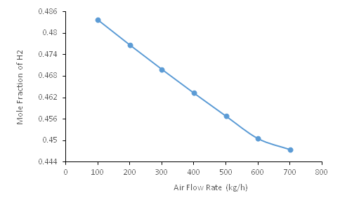
Figure 1. Process Flow Diagram of waste biomass gasification simulation using Aspen Plus.
RESULTS AND DISCURSION
Sensitivity Analysis
Sensitivity analysis for the biomass gasification plant was carried out to study the effect of biomass flow rate, steam flow rate and air flow rate on the yield of products component compositions. The result obtained from the sensitivity analysis are presented in figures 4.1 to 4.12
Effect of Biomass Flow rate on Yield of Product Composition in Oxidation Reactor (PFR 1)
The effect of biomass flow rate on the yield of product components of oxidation reactor are presented as follows:
Effect of Biomass Flow Rate on Yield of Moisture
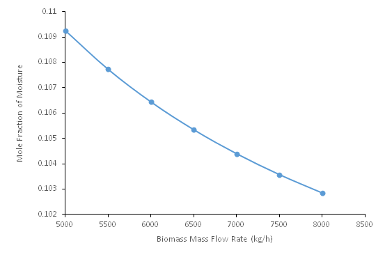
Figure 2: Moisture Composition versus Biomass Flow Rate
Figure 2 shows the effect of biomass flow rate on yield of moisture (H2O). The flow rate of biomass was varied from 5000kg/h to 8000kg/h to see the effect it will have on moisture component and a it is crystal clear from figure 2 that an increase in the flow rate of biomass lead to decrease in the composition of moisture from 0.1092 to 0.1028. There are several reasons for this behavior (a) By increasing the flow rate of biomass, the overall composition of the feed shifts more towards the solid components, effectively diluting the moisture concentration in the feed. As a result, the reactor’s output will contain a lower proportion of moisture relative to other yield products.(b) When you increase the biomass feed rate without altering the reactor’s operational parameters (such as residence time or energy input), the biomass spends less time in the reactor. This reduced residence time can result in incomplete reactions or less effective breakdown of the biomass, including the conversion of moisture to vapor or other products. Since moisture might not fully separate or be processed as efficiently in a shorter time, its proportion in the yield might decrease. (c) As more biomass is added, a higher portion of solid matter is processed. This solid matter can retain moisture, effectively trapping water within the biomass structure. If the reactor’s process does not allow sufficient time or conditions for the water to be fully liberated from the biomass, more water will remain in the solid residue, reducing the moisture content in the reactor’s yield.
Effect of Biomass Flow Rate on Yield of CO
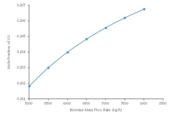
Figure 3: CO Composition versus Biomass Flow Rate
Figure 3 shows the effect of biomass flow rate on yield of CO. The flow rate of biomass was varied from 5000kg/h to 8000kg/h to see the effect it will have on CO component and a it is crystal clear from figure 3 that an increase in the flow rate of biomass lead to a corresponding increase in the composition of CO from 0.1092 to 0.2667. As more biomass is fed into the reactor, more carbon is available for these conversion processes. This leads to a higher production of gases, since the gas-producing reactions (like oxidation, reduction, and cracking) are carbon-driven. When you increase the biomass flow rate, more organic material is available for thermochemical reactions, such as pyrolysis, gasification, or combustion.
Effect of Biomass Flow Rate on Yield of CO2
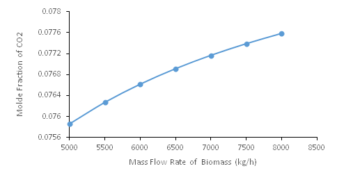
Figure 4: CO2 Composition versus Biomass Flow Rate
Figure 4 shows the effect of biomass flow rate on yield of CO2. The flow rate of biomass was varied from 5000kg/h to 8000kg/h to see the effect it will have on CO2 component and a it is crystal clear from figure 4 that an increase in the flow rate of biomass lead to a corresponding increase in the composition of CO2 from 0.07585 to 0.07758. As more biomass is fed into the reactor, more carbon is available for these conversion processes. This leads to a higher production of gases, since the gas-producing reactions (like oxidation, reduction, and cracking) are carbon-driven. When you increase the biomass flow rate, more organic material is available for thermochemical reactions, such as pyrolysis, gasification, or combustion.
Effect of Biomass Flow Rate on Yield of H2
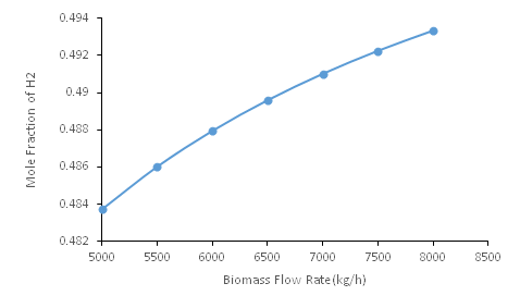
Figure 5: H2 Composition versus Biomass Flow Rate
Figure 4.4 shows the effect of biomass flow rate on yield of H2. The flow rate of biomass was varied from 5000kg/h to 8000kg/h to see the effect it will have on H2 component and a it is crystal clear from figure 5 that an increase in the flow rate of biomass lead to a corresponding increase in the composition of H2 from 0.4837 to 0.4933. As more biomass is fed into the reactor, more carbon is available for these conversion processes. This leads to a higher production of gases, since the gas-producing reactions (like oxidation, reduction, and cracking) are carbon-driven. When you increase the biomass flow rate, more organic material is available for thermochemical reactions, such as pyrolysis, gasification, or combustion.
Effect of Steam Flow rate on Yield of Product Composition in Oxidation Reactor (PFR 1)
The effect of steam flow rate on the yield of product components of oxidation reactor are presented as follows:
Effect of Steam Flow rate on Yield of Moisture
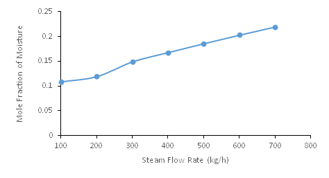
Figure 6: Moisture Composition versus Steam Flow Rate
Figure 6 shows the effect of steam flow rate on yield of moisture. The flow rate of steam was varied from 100kg/h to 700kg/h to see the effect it will have on moisture component composition and a it is crystal clear from figure 6 that an increase in the flow rate of steam lead to a corresponding decrease in the composition of moisture from 0.1092 to 0.2192. The reason for this behavior are as follows: (a) As you increase the flow rate of steam, more water is consumed in these reactions to produce more gases, effectively reducing the amount of moisture left as a product. The higher the steam flow rate, the more reactant is available for these gas-producing reactions, thus decreasing the amount of residual moisture (water vapor) in the output. (b) Introducing more steam can raise the overall temperature in the reactor, especially if the steam is superheated. Higher temperatures can shift the equilibrium of reactions that produce gaseous products over liquid or vapor-phase water. (c) If the steam is being used in a gasification or pyrolysis reactor, the increased flow of steam can enhance the breakdown of biomass. Gasification with steam can lead to more complete conversion of biomass into gaseous products, which reduces the amount of moisture in the product stream because steam is consumed in the formation of gases like H₂ and CO.
Effect of Steam Flow rate on Yield of CO2
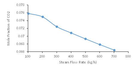
Figure 7: CO2 Composition versus Steam Flow Rate
Figure 7 shows the effect of steam flow rate on yield of CO2. The flow rate of steam was varied from 100kg/h to 700kg/h to see the effect it will have on CO2 component composition and a it is crystal clear from figure 7 that an increase in the flow rate of steam lead to a corresponding decrease in the composition of CO2 from 0.07585 to 0.06647. The reason for this behavior is due to the fact that as more steam is added to the reactor, the total volume of gases (including the steam itself) increases significantly. However, the increase in the production of gaseous products (like CO, CO₂, H₂) may not keep pace with the added steam.
4.2.2 c Effect of Steam Flow rate on Yield of CO
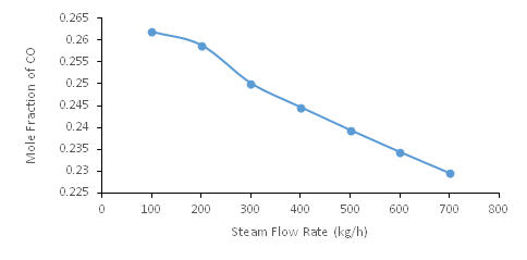
Figure 8: CO Composition versus Steam Flow Rate
Figure 8 shows the effect of steam flow rate on yield of CO. The flow rate of steam was varied from 100kg/h to 700kg/h to see the effect it will have on CO2 component composition and a it is crystal clear from figure 8 that an increase in the flow rate of steam lead to a corresponding decrease in the composition of CO2 from 0.2618 to 0.2295.The reason for this is same as explained in figure 8
Effect of Steam Flow rate on Yield of H2
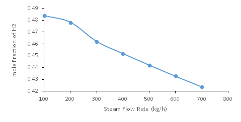
Figure 9: H2 Composition versus Steam Flow Rate
Figure 9 shows the effect of steam flow rate on yield of H2. The flow rate of steam was varied from 100kg/h to 700kg/h to see the effect it will have on H2 component composition and a it is crystal clear from figure 9 that an increase in the flow rate of steam lead to a corresponding decrease in the composition of H2 from 0.4837 to 0.4240.The reason for this is same as explained in figure 9.
Effect of Air Flow rate on Yield of Product Composition in Reduction Reactor (PFR 2)
The effect of Air flow rate on the yield of product components of reduction reactor are presented as follows:
Effect of Air Flow rate on Yield of Moisture
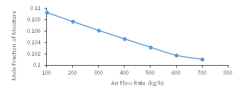
Figure 10: Moisture Composition versus Air Flow Rate
Figure 10 shows the effect of air flow rate on yield of H2. The flow rate of air was varied from 100kg/h to 700kg/h to see the effect it will have on moisture component composition and a it is crystal clear from figure 10 that an increase in the flow rate of steam lead to a corresponding decrease in the composition of moisture from 0.4837 to 0.4240.The reason for this is as follows: (a) As you increase the flow rate of air, more water is consumed in these reactions to produce more gases, effectively reducing the amount of moisture left as a product. The higher the air flow rate, the more reactant is available for these gas-producing reactions, thus decreasing the amount of residual moisture (water vapor) in the output. (b) Introducing more steam can raise the overall temperature in the reactor, especially if the steam is superheated. Higher temperatures can shift the equilibrium of reactions that produce gaseous products over liquid or vapor-phase water. (c) If the air is being used in a gasification or pyrolysis reactor, the increased flow of air can enhance the breakdown of biomass. Gasification with steam can lead to more complete conversion of biomass into gaseous products, which reduces the amount of moisture in the product stream because steam is consumed in the formation of gases like H₂ and CO.
Effect of Air Flow rate on Yield of CO2
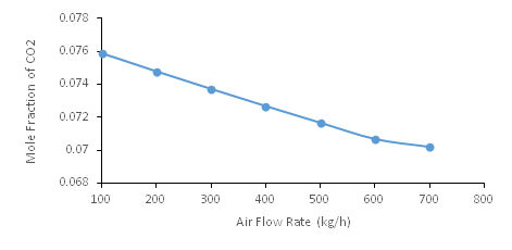
Figure 11: CO2 Composition versus Air Flow Rate
Figure 11 shows the effect of air flow rate on yield of CO2. The flow rate of air was varied from 100kg/h to 700kg/h to see the effect it will have on CO2 component composition and a it is crystal clear from figure 4.10 that an increase in the flow rate of steam lead to a corresponding decrease in the composition of CO2 from 0.07585 to 0.7020.The reason for this is as follows: (a) As you increase the flow rate of air, more water is consumed in these reactions to produce more gases, effectively reducing the amount of moisture left as a product. The higher the air flow rate, the more reactant is available for these gas-producing reactions, thus decreasing the amount of residual moisture (water vapor) in the output. (b) Introducing more steam can raise the overall temperature in the reactor, especially if the steam is superheated. Higher temperatures can shift the equilibrium of reactions that produce gaseous products over liquid or vapor-phase water. (c) If the air is being used in a gasification or pyrolysis reactor, the increased flow of air can enhance the breakdown of biomass. Gasification with steam can lead to more complete conversion of biomass into gaseous products, which reduces the amount of moisture in the product stream because steam is consumed in the formation of gases like H₂ and CO.
Effect of Air Flow rate on Yield of CO
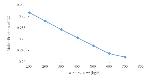
Figure 12: CO Composition versus Air Flow Rate
Figure 12 shows the effect of air flow rate on yield of CO. The flow rate of air was varied from 100kg/h to 700kg/h to see the effect it will have on CO component composition and a it is crystal clear from figure 12 that an increase in the flow rate of steam lead to a corresponding decrease in the composition of CO from 0.2618 to 0.2422.The reason for this is as follows: (a) As you increase the flow rate of air, more water is consumed in these reactions to produce more gases, effectively reducing the amount of moisture left as a product. The higher the air flow rate, the more reactant is available for these gas-producing reactions, thus decreasing the amount of residual moisture (water vapor) in the output. (b) Introducing more steam can raise the overall temperature in the reactor, especially if the steam is superheated. Higher temperatures can shift the equilibrium of reactions that produce gaseous products over liquid or vapor-phase water. (c) If the air is being used in a gasification or pyrolysis reactor, the increased flow of air can enhance the breakdown of biomass. Gasification with steam can lead to more complete conversion of biomass into gaseous products, which reduces the amount of moisture in the product stream because steam is consumed in the formation of gases like H₂ and CO.
Effect of Air Flow rate on Yield of H2
Figure 13: H2 Composition versus Air Flow Rate
Figure 13 shows the effect of air flow rate on yield of H2. The flow rate of air was varied from 100kg/h to 700kg/h to see the effect it will have on H2 component composition and a it is crystal clear from figure 13 that an increase in the flow rate of steam lead to a corresponding decrease in the composition of H2 from 0.4837 to 0.4475.The reason for this is as follows: (a) As you increase the flow rate of air, more water is consumed in these reactions to produce more gases, effectively reducing the amount of moisture left as a product. The higher the air flow rate, the more reactant is available for these gas-producing reactions, thus decreasing the amount of residual moisture (water vapor) in the output. (b) Introducing more steam can raise the overall temperature in the reactor, especially if the steam is superheated. Higher temperatures can shift the equilibrium of reactions that produce gaseous products over liquid or vapor-phase water. (c) If the air is being used in a gasification or pyrolysis reactor, the increased flow of air can enhance the breakdown of biomass. Gasification with steam can lead to more complete conversion of biomass into gaseous products, which reduces the amount of moisture in the product stream because steam is consumed in the formation of gases like H₂ and CO.
CONCLUSION
The simulation of a gasification plant for municipal solid waste (MSW) management in Port Harcourt City using Aspen Plus demonstrated the potential of gasification as an effective waste-to-energy technology. By converting MSW into syngas, the process achieves high thermal efficiency and waste conversion rates, while minimizing harmful emissions compared to traditional methods like incineration. The syngas produced, primarily composed of hydrogen and carbon monoxide, is suitable for energy generation or as a feedstock for synthetic fuel production. The simulation results suggest that gasification could serve as a sustainable and economically viable solution to address the growing waste management challenges in Port Harcourt. Finally sensitivity analysis was carried out to study the effect of varying the flow rate of biomass, steam and air on product component yield for the oxidation reactor.
Conflicts of Interest
The authors declare no conflicts of interest regarding the publication of this paper.
REFERENCES
- Neira, J., Baquero, J., & Alarcón, R. (2016). Waste management in developing countries: Case study of Peru. Waste Management, 56, 7-11.
- Khan, S., Kolachi, M., & Qazi, F. (2019). Impact of landfill sites on human health and environment. Journal of Environmental Science and Health, 54(2), 124-133.
- Leão, R., da Silva, C., & Teixeira, C. (2019). Trends in waste generation and management in Latin American countries. Waste Management, 85, 72-84.
- Hoornweg, D., Bhada-Tata, P., & Kennedy, C. (2013). Environment: Waste production must peak this century. Nature, 502(7473), 615-617.
- Karak, T., Bhagat, R. M., & Bhattacharyya, P. (2012). Municipal solid waste generation, composition, and management: The world scenario. Critical Reviews in Environmental Science and Technology, 42(15), 1509-1630.
- World Bank. (2018). What a waste? :A global snapshot of solid waste management to 2050. Washington, DC: World Bank Publications.
- Wang, L., Wu, H., & Yang, Z. (2018). Assessing the environmental impact of waste-to-energy incineration. Waste Management, 78, 804-817.
- Smith, J., & Jones, P. (2020). Evaluating the efficiency of waste-to-energy incineration processes. Renewable Energy, 145, 123-132.
- Lu, Y., Chen, M., & Li, H. (2018). Thermochemical conversion of waste biomass for syngas production. Journal of Cleaner Production, 181, 691-699.
- Arena, U., Di Gregorio, F., Amorese, C., & Mastellone, M. L. (2019). Environmental performance of alternative thermal waste-to-energy conversion technologies. Waste Management, 37, 41-57.
- Ferrari, A. M., Volpi, L., & Neri, P. (2020). Life cycle assessment of waste-to-energy technologies. Renewable and Sustainable Energy Reviews, 123, 109777.
- Paviet, F., Chazarenc, F. and Tazerout, M. (2009) Thermo Chemical Equilibrium Modeling of a Biomass Gasifying Process Using Aspen Plus. International Journal of Chemical Reactor Engineering, 7 https://doi.org/10.2202/1542-6580.2089
- Begum, S., Rasul, M. and Akbar, D. (2014) A Numerical Investigation of Municipal Solid Waste Gasification Using Aspen Plus. Procedia Engineering, 90, 710-717. https://doi.org/10.1016/j.proeng.2014.11.800
- Pardo-Planas, O., Atiyeh, H.K., Phillips, J.R., Aichele, C.P. and Mohammad, S. (2017) Process Simulation of Ethanol Production from Biomass Gasification and Syngas Fermentation. Bioresource Technology, 245, 925-932. https://doi.org/10.1016/j.biortech.2017.08.193
- Eikeland, M.S., Thapa, R. and Halvorsen, B. (2015) Aspen Plus Simulation of Biomass Gasification with Known Reaction Kinetic. Proceedings of the 56th Conference on Simulation and Modeling, Linköping, 7-9 October 2015, 149-156.https://doi.org/10.3384/ecp15119149
- Eikeland, M.S. and Thapa, R.K. (2017) Stepwise Analysis of Gasification Reactions with Aspen Plus and CPFD. International Journal of Energy Production and Management , 2, 70-80. https://doi.org/10.2495/EQ-V2-N1-70-80
- Guruprasad, R., Renganathan, T. and Pushpavanam, S. (2014) Generalized Thermodynamic Analysis of High Pressure Air Blown Gasifier. Industrial and Engineering Chemistry Research, 53, 18750-18760. https://doi.org/10.1021/ie500898y
- Ramzan, N., Ashraf, A., Naveed, S. and Malik, A. (2011) Simulation of Hybrid Biomass Gasification Using Aspen Plus: A Comparative Performance Analysis for Food, Municipal Solid and Poultry Waste. Biomass and Bioenergy, 35, 3962-3969.https://doi.org/10.1016/j.biombioe.2011.06.005
- Pala, L.P.R., Wang, Q., Kolb, G. and Hessel, V. (2017) Steam Gasification of Biomass with Subsequent Syngas Adjustment Using Shift Reaction for Syngas Production: An Aspen Plus Model. Renewable Energy , 101, 484-492.https://doi.org/10.1016/j.renene.2016.08.069
- Sun, K. (2015) Optimization of Biomass Gasification Reactor Using Aspen Plus.Hogskolen i Telemark, Porsgrunn.
- Fernandez-Lopez, M., Pedroche, J., Valverde, J. and Sanchez-Silva, L. (2017) Simulation of the Gasification of Animal Wastes in a Dual Gasifier Using Aspen Plus®. Energy Conversion and Management , 140, 211-217. https://doi.org/10.1016/j.enconman.2017.03.008
- Kong, X. (2013) Three Stage Equilibrium Model for Coal Gasification in Entrained Flow Gasifiers Based on Aspen Plus. Chinese Journal of Chemical Engineering, 21, 79-84. https://doi.org/10.1016/S1004-9541(13)60444-9
- Kuo, P.-C., Wu, W. and Chen, W.H. (2014) Gasification Performances of Raw and Torrefied Biomass in a Downdraft Fixed Bed Gasifier Using Thermodynamic Analysis. Fuel, 117, 1231-1241. https://doi.org/10.1016/j.fuel.2013.07.125
- Gagliano, A., Nocera, F., Bruno, M. and Cardillo, G. (2017) Development of an Equilibrium-Based Model of Gasification of Biomass by Aspen Plus. Energy Procedia, 111, 1010-1019. https://doi.org/10.1016/j.egypro.2017.03.264
- Lestinsky, P. and Palit, A. (2016) Wood Pyrolysis Using Aspen Plus Simulation and Industrially Applicable Model. GeoScience Engineering, 62, 11-16. https://doi.org/10.1515/gse-2016-0003
- Damartzis, T., Michailos, S. and Zabaniotou, A. (2012) Energetic Assessment of a Combined Heat and Power Integrated Biomass Gasification-Internal Combustion Engine System by Using Aspen Plus®. Fuel Processing Technology, 95, 37-44.