
The Development of a Prototype Trainer Aircraft/Unmanned Aerial Vehicle
- Lawal A. S.
- Kareem B.
- Oladesu O. E.
- 247-263
- Jun 12, 2024
- Mechanical Engineering
The Development of a Prototype Trainer Aircraft/Unmanned Aerial Vehicle
Lawal A. S.*1, Kareem B.2 and Oladesu O. E.3
*1 Department of Mechanical Engineering, Ekiti State University Ado Ekiti,
2Department of Industrial and Production Engineering, Federal University of Technology, Akure, Nigeria,
3Department of Mechanical Engineering, Federal University of Technology, Akure, Nigeria,
DOI : https://doi.org/10.51584/IJRIAS.2024.905022
Received: 22 April 2024; Revised: 18 May 2024; Accepted: 21 May 2024; Published: 12 June 2024
ABSTRACT
The use of generic unmanned aerial vehicle (UAV) is getting common as its small size can easily replace bulky aerial vehicle such as helicopters and airplanes in performing surveillance missions. Spacious room is need to store the UAV and the cost for a generic UAV is relatively high and seldom be owned by normal commercials and industries other than military. The study produced a detachable, light weight, hand launched and low-cost generic unmanned aerial vehicle (UAV). The UAV components were designed to be attachable for launching to perform surveillance activity and detachable for easy storage in small space after service. UAV was manufactured low-cost fiber materials to mold the fuselage. A pair of male and female mold was constructed and the shape of the fuselage was imitated using flexible fiber material. Epoxy cohesive and hardener were used to harden and sustain the shape of the fuselage during the molding process. Finishing was done on the new molded fuselage to refine the aerodynamics flow around the body. The UAV was tested and results showed a satisfactory stability performance.
Keywords: UAV, Surveillance Mission, Flexible Fiber, Molding Process
INTRODUCTION
Birds can fly in sky due to their inherent characteristics and thus they are the dominant in the sky. It is human characteristics to try and dominate everything around him. So, we humans have tried our best over the centuries since the dawn of civilization to achieve the dream of being the dominant force. Having succeeded in the quest of sustained flight through various types and sizes of aircrafts, the first of which is the ‘wright flier’ by the famous Wright brothers, man has ever since set to achieve a bigger goal. Through this thirst for improvement in technology, man has been able to achieve the goal of ‘Unmanned flight’. Unmanned flight happens to be the next stage in the evolution of aircrafts because in the 21st century, unmanned (un-piloted) aerial (airborne) vehicle (means of motion) (UAV) now has a greatly expanded role in many areas of aviation as a result of great technological sophistication.
Over the century, trainer aircrafts have been widely used in training to enhance development of skills in piloting, navigational or war fighting skills in flight crew. Also in an aeronautics class, it enhances learning by showing the different movements of the aircraft in air and different forces acting on it. The feel of the practical experience will make the student more interested and more focused towards learning. This study combines both theoretical and practical knowledge which at the end of the project, a small-scale radio-controlled aircraft will be manufactured. A radio-controlled small-scale aircraft is an aircraft that is controlled remotely with a hand-held controller consisting of transmitter and receiver. The receiver controls the corresponding servos that move the control surfaces based on the position of the joysticks on the transmitter which in turn affect the orientation of the aircraft. From the studies made on the design of an aircraft, the theoretical aspect drawn from the study of aircraft aerodynamics, aircraft structures, aircraft stability and control will be applied in the design of this project. The trainer aircraft to be made can also serve as an unmanned aerial surveillance vehicle.It will be a big contribution to design and fabricate a trainer aircraft which in turn can be used to teach the basic principles of aircraft flight, its aerodynamics and its structures. Also at the military level, trainer aircraft has been introduced as way of improving the training of new and old pilots by allowing them fly the trainer aircraft from the ground and perform different maneuvering in the air. In addition, the UAV has endless applications in all fields. As applied to agriculture, a small-scale farmer who needs an aerial view picture of his farm for planning purpose and some other reasons can make use of UAV with a camera attached to it.
There are a large range of aircraft design texts and guides that assisted the UAV design process. [1] applied conceptual approach in aircraft design. The detail presented in this text gave the general method of analysis and the important points to focus on in UAV design. Niu (1992)’s Airframe structural design concepts were used for additional structural design information. [2] designed wing that was used as both a guide and a source of detailed technical information. Identifying, designing and selection of various wing design parameters were presented extensively in this literature. [3] developed aerodynamics for naval aviators that focused on the basic aerodynamic factors that affects the performance of all aircraft, it also sought to arm the naval aviator with knowledge, training, and exacting, professional attitudes and techniques as majority of aircraft accidents are due to some type of pilot error. [4] presented comparison of various polymers and also Greenhut who gave insights on composites of carbon and glass fiber as reinforcement for engineering structures. This literature provided information on the various types of polymers and composite material, comparing mechanical properties of the various polymers and also of the composites. Studies ([5][6][7][8]) were done on lift generation by air foiled bodies and also the effects of aspect ratio, plan form (wing area) on lift distribution. The concept of employing unmanned aerial vehicles (UAVs) to acquire imagery for disaster research and management has progressed into actual implementation in recent years. UAV usage in disaster assessment, response and management is an active area of research. UAVs have been utilized following ecological, meteorological, geological, hydrological and human-induced disasters. Generally, UAVs have been found useful in both civil ([9][10][11][12][13][14][15] and military ([16][17][18][19]) surveillance.
Although UAVs are a relatively modern concepts, their origin can be traced back to pre-aviation times, the earliest application being surveillance and warfare ([1][20][21]. The timeline of UAVs is outlined as: pre-aviation times (1883-1898), post-aviation times (1903) ([22][23][24][25]).
Characteristics of UAVs currently in service around the globe are Global Hawk Block 20 (Tier 2 Plus) by Northrop-Grumman; Predator by General Atomics Inc.; Taranis by BAE Systems ([26][27] ). The uniqueness of the proposed USAV to be developed does not fit the specification of those stated above but those of Mini Unmanned Air Vehicle (MUAV). The concept of the mini unmanned air vehicle system was that the system could be back-packed, assembled and deployed by no more than two persons. MUAV are prolific largely because they are seen by many people as simple adaptations of model aircraft. Provided that the aircraft has a mass less than 10 kg (originally 5 kg), MUAV were originally expected to be hand-launched and controlled via a laptop computer with display showing video images and navigation and housekeeping data. To this end, the aircraft could not, realistically, have an AUM exceeding 6 kg (for hand-launching) with the total system grossing about 30 kg distributed between two packs. Initially, the aircraft were powered by small petrol- or diesel-powered engines and this required the fuel supply to be included in the backpack(s). More recently, with the development of improved battery technology and lightweight electric motors, this power source makes back-packing more realistically possible. On grounds of safety, the carriage of a supply of rechargeable batteries is preferable, to inflammable fuels. Battery performance in low temperatures might; however, be a cause for concern ([28][29] In this study UAV was constructed using a light weight, cost effective composite structures to consonance with the past studies ([30][31][32][33]).
METHODS AND MATERIAL
2.1 Design Process
The USAV is very much an aircraft but without a pilot sitting in the cockpit hence they both experience the same forces acting on their surfaces though on varying scale. At equilibrium or cruising four forces act on a flying body these include; weight, lift, drag, thrust (Figure 1).
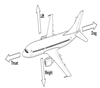
Figure 1. Forces acting on the aircraft, Source: [34]
The components of USAV are:
Fuselage: refers to an aircraft’s main body structure housing the flight crew, passengers, cargo, but for the USAV this will house the payload.
Airfoil: is technically defined as any surface, such as an aileron, elevator, rudder, or wing, designed to obtain reaction from the air through which it moves.
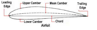
Figure 2. Shape of an airfoil
Aileron: One of a pair of movable control surfaces attached to the trailing edge of each wing tip, the purpose of which is to control the airplane in roll by creating unequal or opposing lifting forces on the opposite sides of the USAV.
Elevator: A movable auxiliary airfoil or control surface designed to impress a pitching movement on the airplane, that is, to cause rotation about the lateral axis.
Rudder: A hinged or movable auxiliary airfoil used to impress a yawing moment on the USAV.
Power Plant: Thrust required to propel the aircraft through the air is generated by the aircraft engine or power plant.
Radio controller: The R/C equipment consists of a transmitter operated by the pilot and the airborne units consisting in a receiver together with one or more servos depending on the number of channels used and a battery pack.
Servomechanisms: Servomechanisms automatically compare the controlled output of a mechanism to the controlling input
Fabrication and assembly of USAV comprises the following hardware.
- 2.4 GHz 6 channel Transmitter and Receiver
- Two MG90S metal gear analog micro servo
- 30 Amp Electronic Speed Controller
- 2200 kV motor
- 6 X 4-inch propeller
- 2200 mAH Lithium Polymer (Li PO) battery
- Control Horns
- Two push rods
- EcoBox 24x48x1 inches polystyrene foam
- Hot glue gun (Electric)
- Cutting knife
- Scotch reinforced strength strapping tape
- Glossy paper
The USAV/Trainer aircraft developed is unique in such a way that its design does not follow the conventional design of planes. The designs were hand drawn (Plates 1 and 2). The reason for drawing with hand is that there was not actually any printer to print the template of the aircraft in required dimension which may lead to design error.
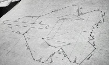
Plate 1: Design drawing I
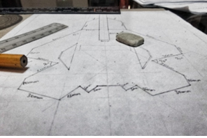
Plate 2: Design drawing II
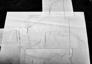
Plate 3: Templates for foam board cutting
The picture in Plate 3 shows half of the aircraft to be built, and the same design was used to build the other half since both halves must be of the same dimension.
2.2 Fabrication Process
1. The plan from of the various part of the USAV frame are first drawn in a large scale say ratio 1:5
2. The sheets containing the various part drawing are then placed firmly on the EPS sheet with the aid of a masking tape.
3. The plan forms are then cut out from the EPS sheets, ensuring maximum use of space.
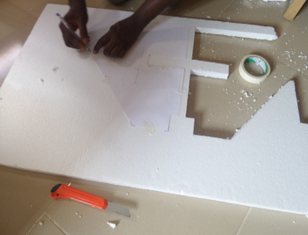
Plate 4: Cutting of Template on EPS Foam4. The various parts of the aircraft are cut out on the EPS foam board (Plates 4, 5) was joined together with hot glue and the ailerons attached to the fuselage with a strapping tape to allow maximum flexibility.
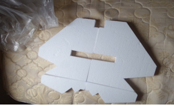
Plate 5: Wing assembly
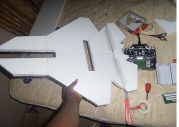
Plate 6: Nose, wing and elevons assembly
5. The rudders were cut out, and were attached to the wing at the end of fabrication (Plate 7).
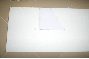
Plate 7: Cutting of stabilizers
6. The fuselage was also cut out using its template (Plate 8).
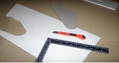
Plate 8: Cutting of fuselage
7. The fuselage was cut out and attached to the wing (Plate 9).
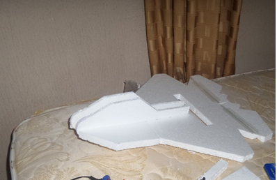
Plate 9: Fuselage assembly
8. The electronics were installed (Plate 10); the servos are first installed, one on each side ensuring symmetry and are attached to the control horns fixed on the ailerons. The servos ensure all the movements of the aileron which also serves as the elevator with the aid of push rods. The movement of the servo is tested before proceeding further.
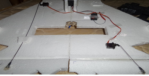
Plate 10: Electronic configuration
9. The brushless motor was fixed in its position cut open on the wing (Plate 11).
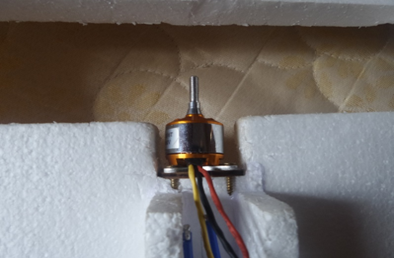
Plate 11: Fixation of brushless motor
10. The stabilizers were fixed on the aircraft i.e. the rudder, at an angle (Plate 12)
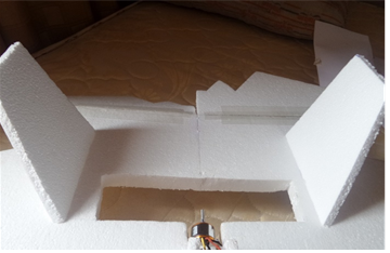
Plate 12: Fixed stabilizers
11. The servos were connected to the receiver which has been bound to the radio controller. Also the electronic speed controller (ESC) was connected to the receiver to power it (Plate 13).
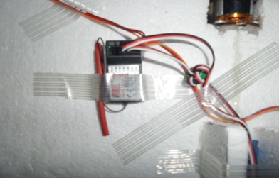
Plate 13: Channels connection to the receiver
12. The motor was connected to the electronic speed controller (ESC) (Plate 14).
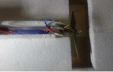
Plate 14: Motor and ESC connection
13. The electronic speed controller was connected to the battery (Plate 15). Battery was disconnected after use.
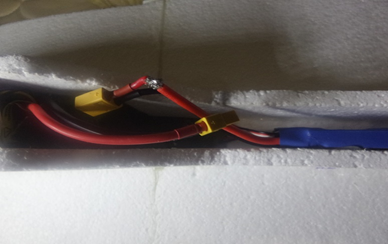
Plate 15: ESC and Battery Connection
14. The electronic connections and the battery was covered to put the battery in a stable position and beautification (Plate 16).
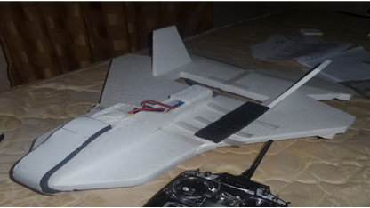
Plate 16: Trainer aircraft
15. The battery which powered the aircraft was recharged using electricity supply (Plate 17).

Plate 17: Battery Charging
16. The RC PLANE was made ready to fly at high speed (Plate 18).
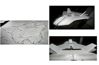
Plate 18: Completed trainer aircraft
2.3 Operation of the Radio Controller
The aircraft was controlled by radio transmitters that generally have two joysticks, one for each thumb. Depending on the design of the transmitter, the sticks were designed to perform different operations. Mode 1 controllers used the left joystick to control the elevator and the rudder, while the right joystick controlled the throttle and ailerons. The right stick was spring loaded to return it to the center, while the left stick was centered horizontally. Moving the left stick forward caused the plane to dive, moving the left stick left turned the plane left, moving the right stick forward caused the plane to increase speed while moving the right stick left caused the plane to roll left (Plate 19).
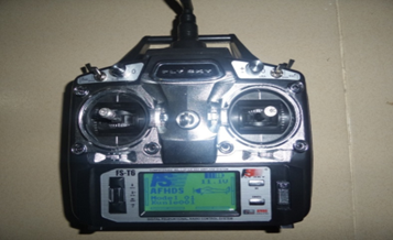
Plate 19: Radio controller
2.4 Electronic Configuration
The electronic installed on the EPS foam board used for the fabrication of the wing and fuselage gave thrust (motor) and control movement (servo). The servos which helped to control the “elevons” (merge of ailerons and elevator) were connected to the receiver on channel 1 and channel 2. The receiver was bonded with the radio controller for synchronization. The speed controller (ESC) was connected to the receiver also, at channel 3. The speed controller (ESC) connected to the battery to power the receiver. The brushless motor was also connected to the speed controller (ESC) which also powered it (Figure 3).
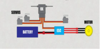
Figure 3: Hardware connections schematic diagram
2.5 Performance Evaluation
(a) Weight Analysis
Empty weight (We)
(We) = Weight of (Receiver + Motor + Servo + Control horn + Servo rod + ESC (Electronic speed controller) + Battery + Expanded polystyrene + Propeller)
We = 19.8g + 62.3g + 18g + 2g+ 31g+198.4g+ 272.15g
We = 607.65g
Empty fraction ratio is given as (Anderson, 2010);
We/Wt =0.6
But
Wt = We +Wp
Where
Wt = Total Weight
We= Empty Weight
Wp = Payload Weight
We/(We+Wp) = 0.6
Wp = (We-0.6We)/0.6
With We = 607.65
Wp = (607.65-364.59)/0.6
= 405.1g
Take-Off Weight = 1012.75g
(b) Wing/Lift Design Analysis
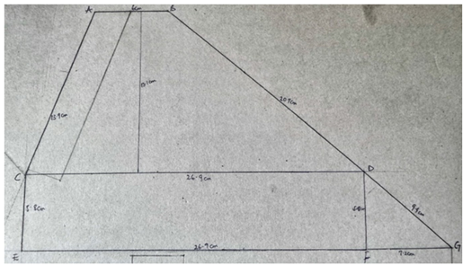
Plate 20: Wing Surface Area
During cruise or level flight, weight and lift generated by the aircraft are in equilibrium
Wt = Lift (L) = ½ PV2 SCL
Where
Wt = Total take-off weight
P = Air density
V = Cruise Velocity
S = Surface area of the wing (Plate 20).
The surface area for the wing
Area of Trapezium = ½ h (b1 + b2)
= ½ x13.1x (6+26.9) = 215.5
Area of the Rectangle = A x B = 5.8 x 26.9 = 156
Area of the Triangle = ½ bh
= ½ x 5.8 x 7.2 = 20.88
Total Wing Area = 215.5 + 156 + 20.88 = 392.38cm2
Note: Wing Span =25. 1 inches
By arranging the wing lift equation, the sectional ideal lift coefficient was calculated as follow
CLC = 2Wt/PX Vcx Vcx S
VC = Velocity during cruise
CLC = (2 x 1012.75 x 9,81)/(1.225 x 30 x30 x 392.38)
= 0.046
Drag is the net aerodynamic force parallel to the relative wind and its source is the pressure distribution and skin friction on the surface. The basic drag equation is as follows:
𝐷𝑟𝑎𝑔 ()=1/2𝜌𝑉2𝑆𝐶𝑑
The force of drag is shown as the product of dynamic pressure, surface area, and drag coefficient (Cd). The drag coefficient in this equation is similar to any other aerodynamic force coefficient it is the ratio of drag pressure to dynamic pressure.
(c) Airfoil Analysis
Analyses of airfoils were done with computational fluid dynamic software known as Java Foil. Java Foil has the ability to generate characteristic curves of airfoils based on the design parameter inputted to it. The performance parameters were then deduced from these curves. The design parameters inputted are:
- Design coefficient of lift (Clmax) = 0.22
- Thickness to chord ratio (t/c) = 0.03
- Aspect ratio (A.R) = 3
- Mach number (M) = 0.05
(d) Aerodynamic Center
The aerodynamic center is the point on the chord where the coefficients of moment are constant- the point where all changes in lift take place. The aerodynamic center is an extremely important aerodynamic reference point and the most direct application is to the longitudinal stability of an airplane. In order for this type airplane to have longitudinal stability, the center of gravity (C.G) must be ahead of the aerodynamic center ([35][36][37]). This very necessary feature can be visualized from the illustrations of Figure 4.
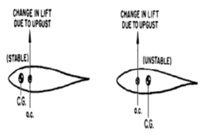
Figure 4: Illustration of airfoil stability
If the two symmetrical airfoils are subject to an up gust, an increase in lift will take place at the aerodynamic center (A.C). If the center of gravity (C.G) is ahead of the aerodynamic center (A.C), the change in lift creates a nose down moment about the C.G which tends to return the airfoil to the equilibrium angle of attack. This stable, “weather cocking” tendency to return to equilibrium is a very necessary feature in any airplane. If the C.G is aft of the A.C the change in lift due to the up gust takes place at the AC and creates a nose up moment about the C.G. this nose up moment tends to displace the airplane farther from the equilibrium and makes the aircraft unstable. The aircraft is similar to a ball balanced on a peak. Hence, to have a stable aircraft, the C.G must be located ahead of the aircraft A.C.
RESULTS AND DISCUSSION
Figure 5 shows the airfoil geometry for a cambered plate developed by JAVA foil for a thickness to chord ratio (t/c) of 0.03, design coefficient of lift (Clmax) of 0.22. Lift has been defined as the net force developed perpendicular to the relative wind. The aerodynamic force of lift on an airplane result from the generation of a pressure distribution on the wing
Figure 5: Airfoil geometry
The typical airflow patterns exemplify the relationship of static pressure and velocity as defined by Bernoulli. Any object placed in an airstream will have air impact or stagnate at some point near the leading edge. The pressure at this point of stagnation will be an absolute static pressure equal to the total pressure of the airstream. As the flow divides and proceeds around the object, the increases in local velocity produce decreases in static pressure. This procedure of flow is best illustrated by the pressure distributions and flow patterns shown in Figures 6 and 7, respectively.
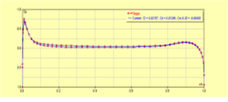
Figure 6. Pressure distribution
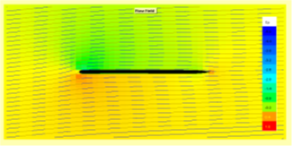
Figure 7. Flow pattern
Table 1: Performance parameters
| Α | Re | CI | Cd | Cm0.25 | L/D | A.C | C.P |
| -10 | 506641 | -0.321 | 0.08828 | -0.001 | -3.633 | 0.260 | 0.248 |
| -8 | 516024 | -0.305 | 0.06702 | -0.001 | -4.548 | 0.256 | 0.247 |
| -6 | 565334 | -0.254 | 0.04977 | -0.001 | -5.100 | 0.255 | 0.247 |
| -4 | 673278 | -0.179 | 0.03611 | -0.002 | -4.959 | 0.266 | 0.241 |
| -2 | 861742 | -0.109 | 0.00815 | -0.003 | -13.383 | 0.262 | 0.219 |
| 0 | 2010000 | 0.012 | 0.00962 | -0.004 | 1.196 | 0.253 | 0.585 |
| 2 | 788448 | 0.132 | 0.00899 | -0.004 | 14.681 | 0.242 | 0.282 |
| 4 | 644591 | 0.198 | 0.03658 | -0.002 | 5.404 | 0.236 | 0.262 |
| 6 | 549262 | 0.272 | 0.05045 | -0.002 | 5.390 | 0.248 | 0.258 |
| 8 | 504662 | 0.322 | 0.06803 | -0.002 | 4.736 | 0.250 | 0.257 |
| 10 | 492627 | 0.339 | 0.08901 | -0.002 | 3.803 | 0.201 | 0.257 |
| 12 | 504767 | 0.318 | 0.11472 | -0.002 | 2.772 | 0.243 | 0.258 |
| 14 | 538030 | 0.280 | 0.14561 | -0.003 | 1.920 | 0.243 | 0.259 |
| 16 | 585941 | 0.236 | 0.16874 | -0.003 | 1.401 | 0.242 | 0.263 |
| 18 | 643164 | 0.196 | 020289 | -0.003 | 0.967 | 0.242 | 0.267 |
| 20 | 708092 | 0.162 | 0.22279 | -0.004 | 0.726 | 0.242 | 0.272 |
The values (Table 1) were then plotted using the excel sheet to produce the lift characteristic trends. Plotting the lift coefficient of the aircraft wing plan form versus angle of attack (α˚) produces the graph of Figure 8. Since the effects of speed, density, area, weight, altitude, etc. are eliminated by the coefficient form; an indication of the true lift capability is obtained. Each angle of attack produces a particular lift coefficient since the angle of attack is the controlling factor in the pressure distribution. Lift coefficient increases with angle of attack up to the maximum lift coefficient Clmax and, as angle of attack is increased beyond the maximum lift angle, the airflow is unable to adhere to the upper surface. The airflow then separates from the upper surface and stall occurs.
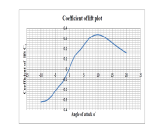
Figure 8 Coefficient of Lift Plot
Plotting the drag coefficient of the aircraft versus angle of attack (α˚), produces the graph shown in Figure 9. At low angles of attack, the drag coefficient is low and small changes in angle of attack create only slight changes in drag coefficient. At higher angles of attack, the drag coefficient is much greater and small changes in angle of attack cause significant changes in drag. As stall occurs, a large increase in drag takes place.
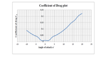
Figure 9. Coefficient of Drag Plot
The aerodynamic center (A.C) on Table 1 has a maximum of 50% and a minimum of 20% chord, the aircraft center of gravity (C.G) has to be placed forward of 20% chord for the aircraft to have longitudinal stability.
CONCLUSION
The UAV is a complex combination of advanced technologies in aerodynamics, structures, materials, stability and system integration. There are still further design considerations to be studied in the development. It was expected that a sound design and model put in place for implementation to enable emergence fast and high operational system and airframe integration, and creating enablement for new technologies to strive with the goal of mitigating delay in receiving materials for production of the USAV due to custom policies.
REFERENCES
- E. Ackerman 2011. “Japan Earthquake: Global Hawk UAV May Be Able to Peek Inside, Damaged Reactors.“ Spectrum. IEEE, 17 Mar. 2011
- J. D. Anderson 2010. “Fundamentals of Aerodynamics”, McGraw-Hill, Fifth Edition.
- B. Etkin 1996. “Dynamics of Flight, Stability and Control”, Third Edition, Wiley.
- J. R.Frankenberger 2008. “Low-Altitude Digital Photogrammetry Technique to Assess Ephemeral Gully Erosion”. Geoscience and Remote Sensing Symposium, 2008. IGARSS 2008. IEEE International.
- M. Huber 2010. “Evergreen supports UAV team mapping Haitian Relief” Aviation International News. March 2010.
- G.R. Ian 2013. “The rate of the predator empire: Tracing the History of U.S Drones”, understanding empire, http://understandingempire.word press.com/2-0-G-brief-history-of-US-Drones/.html, May 28 2014
- L. R.Jenkinson 2000. “Civil Jet Aircraft Design”, Butterworth-Heinemann.
- K. P.Kampf. 2000. “Design of an unmanned reconnaissance system”. ICAS 2000, Harrogate UK.
- J. Katz 1999. “Low-Speed Aerodynamics”, McGraw-Hill.
- I Kruggl.2010. “Networked UAVs as aerial sensor network for disaster management applications.“Elektrotechniknd Information Technik 127(3): 56-63.
- A. Lennon 1996. “Basics of R/C model aircraft design”. Air Age Media, Connecticut, U.S.A Mechanical Engineering Handbook Ed. Frank Kreith Boca Raton: CRC Press LLC, 1999
- R. Murphy, 2010.”Have Robots been used in Previous Earthquakes?” Center for Robot-Assisted Search and Rescue. Texas Agricultural and Mechanical University.
- C.Y. Niu 1989. “Airframe structural design”.Conmilit press LTD Hong Kong.
- NOVA2014. “Spies that fly – Timeline of UAVs” http://www.pbs.org/wgbh/nova/spiesfly/UAVs.html, May 28 2014
- D. Potts 1999.“The Observer Concept”, Proceedings of the 14th Bristol International UAV Systems Conference, University of Bristol, UK, 1999.
- K. Pratt 2006. “Requirements for Semi-Autonomous Flight in Miniature UAVs for Structural Inspection”. AUVSI’s Unmanned Systems North America. Orlando, Florida, Association for Unmanned Vehicle Systems International.
- D. P. Raymer 1992. “Aircraft Design: a conceptual approach”. American Institute of Aeronautics and Astronautics Inc., Washington D.C.
- A.Reg 2010. “Unmanned Air Systems”, John Wiley & Sons Ltd.
- M. Sadraey2009. “Aircraft Performance Analysis”, VDM Verlag Dr. Müller.
- R. S. Shevell 1989. “Fundamentals of Flight”, Prentice Hall”, Second edition.
- E. Steimle 2009. Unmanned marine vehicle use at Hurricanes Wilma and Ike. OCEANS 2009, MTS/IEEE Biloxi – Marine Technology for Our Future: Global and Local Challenges.
- D. Steinbach 1996 “Comment on Aerodynamic Characteristics of a Two-Dimensional Airfoil with Ground Effect”, Journal of Aircraft, Col. 34, No. 3, pp. 455-456.
- T. Suzuki 2008. “Real-time hazard map generation using small unmanned aerial vehicle”. SICE Annual Conference.
- Tom Scheve2014. “How the MQ – Reaper works – A brief History of UAVs”, http://science.howstuffworks.com/reaper1.htm. Unmanned Vehicles Handbook, The shepherd Press Ltd, UK. 2004.
- VT Group2011. Devastating Earthquake in Haiti: Pioneering Technology Application Saves Time & Resources. VT Group Portland, Oregon, USA. http://www.vt-group.com/unmanned. Accessed: 19 Aug. 2014.
- Wikipedia “History of Unmanned Aerial Vehicles” http://en.m.wikipedia.org/wiki/History of Unmanned aerial Vehicle. May 28 2014
- Yang et al., 2010 Autopilots for Small Unmanned Aerial Vehicles: A Survey, International Journal of Control, Automation, and Systems, 8(1), 2010, Pp 36-44.