
In-depth IoT-based Home Automation System for Ghana’s Context
- Mohammed Y. Umaru
- Emmanuel Effah
- Minta Frederick
- Essilfie Albert
- 521-530
- Dec 20, 2023
- Information and Communication Technology
In-depth IoT-based Home Automation System for Ghana’s Context
Mohammed Y. Umaru, Emmanuel Effah, Minta Frederick, and Essilfie Albert
Smart System and Innovation Laboratory, UMaT, Ghana
DOI: https://doi.org/10.51244/IJRSI.2023.1011043
Received: 23 November 2023; Accepted: 25 November 2023; Published: 20 December 2023
ABSTRACT
This paper presents an In-depth IoT-based Home Automation system (IIHAS) for Ghana’s context. The system comprises of a number of components including a Raspberry Pi 3 Mini Computer, a microcontroller, sensors, actuators, and a mobile application. The paper discusses the design of the system, the different components involved, the communication protocols used, the security measures implemented, and the challenges faced in the development of the system. The paper further evaluates the system based on its performance, usability and reliability. The paper concludes by discussing the potential of the system in improving the quality of life of the Ghanaian population.
Index Terms Electrical Consumption Monitoring, Fire and Gas Leakage Monitoring, Intruder Detection
INTRODUCTION
HANA has witnessed several spikes in electricity tariffs and some of the most commonly known causes of fire outbreaks that includes faulty electrical cables, gas leakage, electrical cables and human error. Since 2015, electricity tariffs have increased over 100%. According to statistics from the Electricity Company of Ghana’s website, tariffs have moved from 15 pesewas per unit to 34 pesewas per unit in the past few years [1]. ECG equates the need for the hike in prices to rising cost of production, growing energy demand and the fall in the cedi. Since the inception of these increments, customers have been disgruntled and disheartened by the new changes introduced by the Electricity Company of Ghana (ECG). In an attempt to help customers deal with the increase in tariffs, ECG has advised customers to reduce their elec- tricity consumption. The use of home automation systems to monitor and reduce electricity consumption has proven to be an effective solution. Unfortunately, this type of system may be expensive to import and has not been widely designed and developed for the Ghanaian community. As a result of the increasing interest in the concept of Internet of Things (IoT), home automation has become a field of application and intense research. However, very little literature exists on the implementation of home automation in Ghana.
Additionally, there has been a growing desire for a re-motely controlled electric fire outbreak and leak-detection system for gas cylinders. According to the GNFS (Ghana National Fire Service), there were about 2,469 fire outbreaks within the first quarter of 2016. Of this number,145 of these fires were said to have been electrical fires and 70 of these electrical fires were domestic-related fires [2]. Most cases of fire outbreaks are associated with human errors; forgetting to switch off certain appliances such as irons, electrical heaters, kettles, lights, and gas cylinders or overfilling them at gas stations and these things have the potential to cause a fire. A research and feasibility study conducted in 2013 by Ming Yan and Hao Shi focused on controlling devices connected to a Bluetooth controller module [3]. The user terminal of this system was connected to the controller via an android phone’s native Bluetooth capability. However, one major problem with this system was range. The Bluetooth technology has not been designed to cover large distances and hence limited the possibility of remotely controlling the system.
Another similar project dealt with developing an afford- able solution that will enable remote control of home appli- ances and also serve as a security system [4]. This project focused on using SMS to control the monitoring subsystems. It was built using a microcontroller, General Packet Radio Service (GPRS) modem/ cell phone and a sensing unit. The project was undertaken by Ciubotaru-Petrescu, Chiciudean, Cioarga, and Stanescu in 2006. One of the downsides iden- tified in this approach was the inability to transmit several commands in one SMS, hence, increasing the latency of the system as it has to go through several different SMS messages.
This paper focuses on the potential of using an IoT-based home automation system in Ghana’s context. Home automa- tion is a system that allows the user to monitor and control various aspects of the home, such as lighting, temperature, security, and other devices. IoT-based home automation sys- tems are becoming increasingly popular and are being used to enhance the comfort, convenience, and safety of homes in Ghana. This paper will discuss the potential benefits of using an IoT-based home automation system in Ghana, as well as the potential challenges that need to be addressed in order to make it successful.
Benefits Of Implementing An Iot-Based Home Automation System
The use of an IoT-based home automation system can offer numerous benefits to Ghanaian households.
- Improved convenience: Home automation systems give users the ability to control their appliances from any location, at any This added convenience can improve the quality of life of any household.
- Enhanced safety: Automating the home can help to increase safety by providing alerts in case of intruders or fires. Security cameras, motion sensors and door locks can all be integrated into the home automation system to provide extra protection.
- Energy savings: Automating the home can help to reduce energy costs by scheduling appliances to turn off and on or adjusting the temperature in the home.
- Increased Comfort: Home automation systems allow users to personalize the environment of their home. This can include setting the perfect temperature, cre-ating the perfect lighting, and controlling the music.
- Increased Productivity: Automating the home can help to increase productivity by automating tasks such as setting alarms, controlling the TV, and more. This can help to free up more time for other activities.
OVERVIEW OF IOT-BASED HOME AUTOMATION SYSTEM (IIHAS) MECHANISMS
The fundamental concepts that is making this home au-tomation technology possible is Internet of Things (IoT). This essentially makes it possible for objects to collect data from the environment and communicate it by harnessing underlying technologies such as embedded devices, perva- sive and ubiquitous computing, communication protocols and sensors networks. Home automation can be defined as a system implemented at a residential place whereby the intention is to make the place intelligent so that energy is conserved and security is maintained [5], [6]. Since IoT- based technologies are application- and context-specific, a new context-relevant approach is required for the case of Ghana. For instance, most HAS IoT applications in Europe and America rely on Wi-Fi or Cellular-based communication technologies, which cannot be the case in Ghana due to lack of adequate coverage and the cost of sustaining these paid technologies. A more suitable solution must utilize freely available and location-unrestricted communication technolo- gies such as LoRa, Bluetooth Low-Energy (BLE), Global System for Mobile Communications (GSM), among others.
PROPOSED IIHAS SYSTEM
In this section, we present a detailed overview of the physical design, deployment, and validation/testing of the proposed IIHAS testbed with a use-case for the Hospitality Industry of Ghana. The block diagram of the proposed system is illustrated in Figure 1.
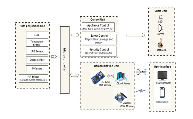
FIGURE 1. Block Diagram of Proposed System
Our IIHAS performs four main functions, which include the following:
Data Acquisition Unit
Software Tools: The necessary software tools required for the system implementation includes Raspbian operating system, Python IDLE, Open CV, computer vision software extension for python with Haar cascade classifier and object detection, Canny edge detector. The detail implementations of these tools are presented in later subsections.
Hardware Tools: The hardware tools include the following:
Raspberry Pi Board: is a credit card sized single- board Generation 3 Model B also has 4 USB ports, 1 GB RAM, USB camera interface and an HDMI interface and 40 GPIO allows us to control and interact with real world.
Pi Camera V2: The camera plugs directly into the USB connector on the Raspberry Pi. It’s able to de- liver clear 8MP resolution image, or 1080p HD video recording at 30fps. This USB camera which has no infrared filter making it perfect for taking infrared photographs or photographing objects in low light (twi- light)
Smoke Sensor: Smoke sensor is used to detect the smoke or fire in the house. It has 3 and sometime 4 pins.
a) Pin 1 is VCC Pin and is used to supply voltage (3.3V to 5.3V)
b) Pin 2 is (GND) Ground Pin
c) Pin 3 is an analog output
d) Pin 4 is a digital out
Smoke sensor is connected to NODE MCU ESP8266 WiFi Module which was programmed in such a way that when the sensor detects fire or flame it will trigger the NODE MCU ESP8266 module and NODE MCU send alert to an App like (Fire in House). Node MCU is connected to internet through gateway or router. The App is used to receive alerts. Sketch or Program that was uploaded to NODE MCU ESP 8266 WIFi Module contains.
a) Auth Code : auth code is send through email when we create project in Blynk
b) SSID: SSID is our WiFi name
c) Password: give password of WiFi
PIR Motion Sensor: PIR Motion Sensor is used in this project to detect suspicious / unwanted movement. PIR Motion sensor is small in size, easily available, easy to use therefore used in large no of project. Its output when PIR Motion sensor detects movement then (dig- ital high) otherwise (Digital Low) and its sensitivity range is up to 20 feet’s Power: 3.3v or 5v There are three pins in PIR Motion sensor VCC, Out and GND
MQ-6 Gas Sensor: The MQ-6 gas sensor is used to detect propane, butane, and liquefied petroleum gas (LPG) gas. The MQ-6 gas sensor can detect gas con- centrations anywhere from 200 to 10.000 ppm. MQ-6 sensor requires a Direct Current (DC) voltage of 5 Volts and has high sensitivity and fast response time.
Temperature and Humidity Sensor: DHT11 Temperature and Humidity Sensor is used in the developed system. It has a calibrated digital output signal with capability of temperature and humidity sensor. It has a supply voltage of 5 V, the temperature range of 0-50 °C error of ± 2 °C and humidity of 20-90% RH ± 5% RH error. The pin description of the sensor is shown in Figure 7.
Control Unit
The design proposes an control unit system that enables the user to control home appliances remotely, monitor gas leakage and in. This includes:
1) Electricity Cosumption Subsystem – Home appliances like lights, fans, bulbs, air conditioners, washing ma- chines and refrigerators are control remotely with the help of mobile phones. For the said purpose android base application is install on cell phone and user can switch on and off home appliances.
2) For safety purposes, the fire detection and gas leak- age detection systems can be install in home. These systems detect fire and gas leakage and intimate user timely and help in avoiding accidents.
3) Intruder detection system to detect the unwanted move- ment in homes and to intimate us timely in case of emergency. Smart home operations are usually control through the mobile devices like smart phones, PDA’s, tablets etc to users via internet-connected mobile de- vices.
Communication Unit
Cloud: The cloud unit with the applications layer, consists of a server (local or remote) that hosts the applications layer, event data analytic engines, security protocols, robust IoT applications, user interface, and event database. The high-resource-demanding data processing tasks are mostly executed in the cloud-hosted applications which are well- equipped to:
1) Receive extensive quantities of data from devices via gateway solutions;
2) Process and store the data;
3) Enable communication with devices;
4) Control registration of devices that can connect to the application;
5) Provide monitoring and data analytical services.
IoT: This component is the system responsible for communica-tion between devices connected in the system and the user’s interface with the help of the cloud broker. The switchboard which will be running an MQTT protocol library and con- necting to an MQTT broker over a network. The MQTT libraries are available for implementation in Java, C++, C or JavaScript. The device would need to have a TCP/IP stack which it could communicate via MQTT. In designing this system, the following design goals were considered;
- Low latency (speed)
- Low Power Consumption
- Low cost
User Interface: Users can live-monitor the driver’s conditions and execute control actions via software interfaces such as webpage of custom app. Additionally, a presentation or business intelligence layer may be added to coordinate the activities of non-technical business users via dashboards and reports rather than with the application layer itself. The testbed implementation was created based on this conceptual architectural framework.
Alert Unit
The alert system allows users to receive alert from the various components of the system that includes Electricity Consump-tion alert, Fire and Gas Leakage alert (Safety) and Intruder Detection alert (security).
Electricity Consumption Alert: The electricity consumption subsystem should be connected to an alert system which can be triggered if the consumption exceeds a certain threshold. This alert system can send out an alert in the form of an email, text message, or other form of notification. The alert system can also be set up to trigger other actions, such as shutting off power to the subsystem or notifying the utility company of a possible issue. This alert system can also be used to track electricity consumption trends over time, which can help identify any potential issues or opportunities for efficiency.
Fire and Gas Leakage Alert (Safety Alert):
The alert system for a fire and gas leakage subsystem should be designed to detect any changes in the system and alert the appropriate personnel in a timely manner. The sys- tem should be designed to detect any changes in temperature, pressure, or other environmental conditions in order to alert personnel of possible fire or gas leakage. The system should also be capable of detecting any movements or sounds that could be indicative of a fire or gas leak.
The alert system should be designed to be as automated as possible, so that the appropriate personnel can be alerted without the need for manual input. The system should be capable of sending out alerts via email, text message, or other notification services. Additionally, the alert system should be able to send out notifications to multiple personnel simultaneously so that response times can be minimized.
Finally, the alert system should be designed to be as flexible as possible, so that it can be adapted to different environments and conditions. This includes the ability to set different thresholds for different conditions, as well as the ability to customize the alert messages sent out.
Intruder Detection Alert (security Alert):
The alert system for an intruder detection subsystem should be designed to ensure that any unauthorized access or movement is detected and reported immediately. The alert system should be set up to alert the security personnel or appropriate authorities in the event of an intruder. Depending on the type of system and the level of security, the alert system may include:
1) Video surveillance systems: Video surveillance sys- tems can be set up to send alerts to security personnel or authorities if an intruder is detected. The alert may be sent via text message, email, or other notifications.
2) Motion sensors: Motion sensors can be used to detect movement in an area and trigger an alert. This type of sensor is typically used in areas where high levels of security are needed.
3) Door and window sensors: Door and window sensors can be used to detect when an unauthorized person opens or closes a door or window. The alert may be sent to the security personnel or appropriate authorities.
4) Access control systems: Access control systems can be set up to ensure that only authorized personnel have access to certain areas. If an unauthorized person attempts to gain access, an alert can be sent to the security personnel or appropriate authorities.
5) Alarm systems: Alarm systems can be used
PROPOSED SOFTWARE DESIGN AND IMPLEMENTATIONAL METHODOLOGY
This section provides a detailed description of the processes used in the implementation of the In depth IoT-based Home Automation System. The implemention of the system is dev- ided into 3 major areas; the actual development of the front- end application, communicating hardware and data collection engine. For each subsection, the libraries and technologies used are brought to light. The client-server architecture was used in the development of the system. The Figure 3.2 shows a detailed architectural diagram of the entire IIHAS system.
The subsystem has a system that is being used to do two things; send instructions to the cloud broker via MQTT and sending HTTP requests to the PHP server to retrieve data from the database for the construction of its graphs and charts. The GSM module provides the microcontroller with the ability to connect to the cloud broker to receive instructions sent from the user terminal and to publish the following;
1) electricity consumption values based on readings from the PZEM-004T modules;
2) detect flame or fire and intimate the user by sending message or alert;
3) detect the intruder or suspicious activity and intimate the user timely.
After processing instructions received from the broker, the microcontroller uses the relays to cut power going to a target appliance connected to the system, the LCD screen is used to display messages and readings from the microcontroller directly on the board and the Buzzer or Alarm is turned on.
Electricity Consumption Subsystem
The Electricity Consumption Subsystem will be made up of four communication components that includes the following;
1) The IoT devices switchboard which will receive and transmit signals to and from appliances.
2) The cloud service which will handle communication between user interface and switchboard devices.
3) The PHP server side and MySQL database which will handle storage of historical data and transmission of data to mobile application.
4) The mobile application used by the user to interface with the entire system.
The system will allow users to monitor their electricity consumption in real-time as well as control all home appli- ances.
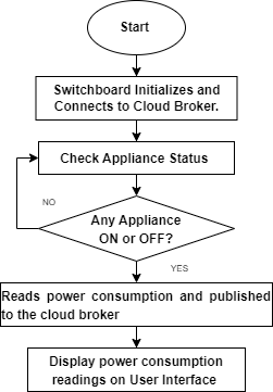
FIGURE 2. Flowchart for Electricity Consumption reading Subsystem
As illustrated in the flowchart in Figure 2, the user is able to monitor electricity consumption of each individual appliance connected to the subsystem. when the is connected, the user would be able to view total power consumption limit for the day or month of all devices via the interfaces. The user should then be able to select any appliance to view its individual electricity consumption reading. This will be regarded as the threshold within which the user is happy with his/her consumption. Whenever consumption exceeds this threshold the user would be alerted. The operational sequence of the Electricity Consumption subsystem is illustrated in Figure 2.
Fire and Gas Leakage Subsystem
The Fire and Gas Leakage Subsystem is a safety system used to detect and respond to different types of fire and gas leakage emergencies. It is typically composed of sensors, controllers, and alarms that can detect a variety of fire and gas leakages. The system also includes an interface for operators to monitor the system and manage the response. This system is used in many industrial settings to protect personnel and equipment from potential hazards. In some cases, the system may be integrated with other safety systems such as evacuation plans, building access control, and sprinkler systems. The Fire and Gas Leakage Subsystem is a critical component of any safety program and is essential for protecting people, property, and the environment.
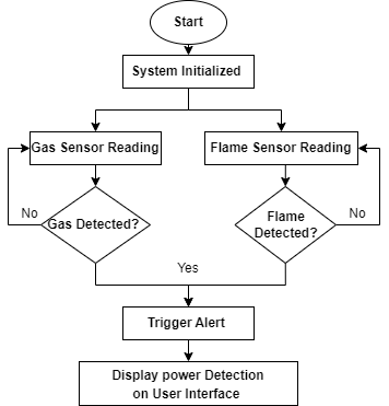
FIGURE 3. Flowchart for Fire and Gas Leakage Reading Subsystem
The Fire and Gas Leakage system flow chart begins with an initial detection of a fire or gas leakage. Once the fire/gas is detected, an alarm is triggered and the system is activated. The system then immediately shuts off gas valves and fans to prevent the spread of fire or gas and simultaneously activates ventilation systems to replace the air in the space with fresh air. If a fire is detected, the system will also activate any fire suppression equipment such as sprinklers.
At the same time, the system will initiate an alarm noti- fication to alert people of the emergency. This could be in the form of an audible alarm, a flashing light, a text message, or any other form of notification. Once the alarm has been triggered, the system will then monitor the area for any changes in the fire or gas levels and will continue to take preventative measures until the situation is resolved.
Finally, the system will reset itself once the emergency has been resolved. This includes resetting any valves, fans, and ventilation systems, as well as restoring any fire suppression equipment. The system will then remain in standby mode, ready to be activated in the case of another emergency.
Intruder Detection Subsystem
The intruder detection subsystem is a security system de- signed to detect and alert personnel when intruders enter a designated area. This system is used in commercial, residen- tial, and industrial settings to increase security and provide early warning of potential threats. The system typically con- sists of motion detectors, door and window sensors, cameras, and alarms. Motion detectors detect movement within the vicinity of the area, while door and window sensors detect when a door or window has been opened or closed. Cameras provide a visual representation of the intruder, while alarms sound off when an intruder is detected. The system can be configured to alert personnel through a variety of methods such as text messages, emails, and phone calls.
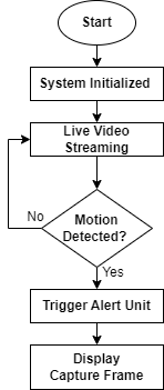
FIGURE 4. Flowchart for Intruder Detection Monitoring Subsystem
The intruder detection subsystem flow chart shows the steps used to detect and respond to potential intrusions. It begins by monitoring the environment for signs of intrusion, such as motion, audio, visual, or temperature changes. If an anomaly is detected, the system triggers an alarm. The alarm can be configured to alert a security or monitoring service, or to activate an automated response such as locking doors or turning on lights. The alarm can also be configured to send notifications to people who are authorized to respond to the incident. Once the alarm is triggered, the system can be configured to record video and audio of the incident, and send it to the monitoring service. The monitoring service can then take the appropriate action, such as dispatching police or other responders. The system can also be configured to provide a detailed report of the incident, including a timeline and other relevant information. Finally, the system can be configured to provide feedback to the user, such as a detailed report of the incident or a list of recommended security measures.
EXPERIMENTAL VALIDATIONS AD RESULTS
The experimental validation and results for IoT home au-tomation were conducted to evaluate the effectiveness of the system as illustrated in Figure 3. The system was tested by measuring the performance of the system in terms of accuracy, latency, scalability, and reliability.
Accuracy: The accuracy of the system was evaluated by testing the accuracy of the sensors used in the system. The accuracy was tested by placing the sensors in different locations and measuring the temperature, humidity, and other environmen- tal conditions. The results showed that the accuracy of the sensors was within acceptable limits.
Latency: The latency of the system was evaluated by testing the time taken for the system to process data from the sensors and send the results back to the user. The results showed that the system had an acceptable latency time.
Scalability: The scalability of the system was evaluated by test- ing the ability of the system to scale up and down according to the user’s requirements. The results showed that the system had an acceptable scalability.
Reliability: The reliability of the system was evaluated by testing the ability of the system to stay up and running even in the event of system failures. The results showed that the system had an acceptable level of reliability.
Overall, the results showed that the system had an accept- able performance in terms of accuracy, latency, scalability, and reliability as illustrated in Figure 3. The system was found to be reliable and effective in providing automated home solutions.
CONCLUSION AND FUTURE WORKS
The implemented system provides an efficient and secure way to automate home tasks. It can be used to monitor, con- trol, and manage connected devices. The system is also user- friendly with its intuitive interface and voice commands. In addition, the system is secure and reliable with its encryption technology and secure communication protocols.
Overall, the I depth IoT Home Automation system offers a comprehensive solution for users to monitor and control their home. However, there are still some areas in which the system can be improved. For example, the system can be enhanced to include more advanced features such as predic-tive analytics and AI-powered automation. Additionally, the system can be improved to support more connected devices and provide better energy management.
In the future, IIHAS can continue to improve the system by integrating more advanced features and expanding its range of connected devices. With the advancements in technology, IIHAS can also explore the potential of applying AI and machine learning to further enhance the system’s capabili- ties. Finally, IIHAS can continue to focus on improving the system’s security and reliability to ensure that users’ data remains safe and secure.
REFERENCES
- K. Blankson and M. Lartey, “Road traffic accidents in ghana: contributing factors and economic consequences,” Ghana Med J, vol. 54(3.), pp. 1–12, 2020.
- Ivers, K. Brown, R. Norton, and M. Stevenson, “Road traffic injuries,” International Encyclopedia of Public Health, pp. 393–400, 2016.
- Mittal, K. Kumar, S. Dhamija, and M. Kaur, “Head movement-based driver drowsiness detection: A review of state-of-art techniques,” March 17- 18, 2016, pp. 903–908.
- Colic, Marques and B. Furht, “Design and implementation of a driver drowsiness detection system a practical approach,” International Conference on Signal Processing and Multimedia Applications (SIGMAP), pp. 241–247, 2014.
- Effah, O. Thiare, and A. Wyglinski, “Multi-objective optimization mod- eling of clustering-based agricultural internet of things,” in 2020 IEEE 92nd Vehicular Technology Conference (VTC2020-Fall). IEEE, 2020, pp. 1–5.
- Effah, O. Thiare and A. M. Wyglinski, “Energy-efficient multi hop rout- ing framework for cluster-based agricultural internet of things (CA-IOT),”