
Design and Characterization Analysis of a Corona Virus Shaped Microstrip Multiband Patch Antenna
- SK Tanchin Rahman
- Priom Das
- Shekh Shahed Jiban
- Anik Dey
- 865-873
- Mar 18, 2025
- Engineering
Design and Characterization Analysis of a Corona Virus Shaped Microstrip Multiband Patch Antenna
SK Tanchin Rahman, Priom Das, Shekh Shahed Jiban, Anik Dey
Port City International University
DOI: https://doi.org/10.51244/IJRSI.2025.12020067
Received: 07 February 2025; Accepted: 12 February 2025; Published: 18 March 2025
ABSTRACT
In this proposed paper, a Corona Virus shape of microstrip patch antenna designed without using DGS which is proposed for multiband operation for the VHF (30-300 MHz), UHF (300-1000 MHz), L-band (1000-2000 MHz), and S-band (2000-4000 MHz) applications. The antenna is 40 mm × 40 mm × 0.96 mm and Rogers R03003 is used as a substrate. Also, copper is used for both the patch and the ground plane. Initiation of a Corona Virus-shaped structure with modified upper slots develops in the patch’s center. There are 25 resonant frequencies in all for the antenna. With a maximum gain of 12.7 dBi at 36.7 GHz and an average gain of 8.1 dBi. Thus, the VSWR of this Virus-shaped patch antenna can fulfill the criteria of the multiple intended applications while taking into account all the parameters, including bandwidth, high gain, higher return loss, reflection coefficient, and impedance matching.
Keywords: Corona virus shape, DGS, Multiple bands, Resonant frequency.
INTRODUCTION
An antenna is defined by Webster’s Dictionary as “a usually metallic device (as a rod or wire) for radiating or receiving radio waves” [1].
Due to the improvement of wireless communication in today’s world, the demand for multiband antennae has increased. Strong wireless communication requires high frequencies antenna. But the cost of a high-frequency antenna is high. So it’s necessary to bring the antenna into the market with low cost and simple design for multidimensional purposes. The 5G antenna is operated at low (600 – 900 MHz) and mid (1.7 – 4.7 GHz) mm-wave bands [2]. In that case, the demand for a high-frequency range with a large amount of bandwidth is necessary. So, this Corona virus-shaped antenna may be a solution for the latest developments in 5G technology.
In addition, multiband antennas are widely preferred in wireless applications such as encrypted communications frameworks, space station communication systems, and other wireless applications [3]. For multiple frequency bands, different antennas are usually required [4] – [5]. The development of patch antenna is still developing, and several enticing solutions for using a reliable antenna that can operate in several frequency bands are already being proposed. Similarly, to the peer characteristics of such patches, multiband contributes to reducing dimensions, and subsequently mass and area. [5]. New results show that the antennas have remarkable multiband characteristics and lower resonance frequencies [5]- [6].
In this paperwork, the Corona Virus shaped patch of the antenna has been designed by using RogerRO3003 substrate. A well-designed capacitive gap in various forms can improve the antenna’s effectiveness, resonance frequency, high gain, and efficiency. So, a new small rectangular patch on both sides of the transmission line has been added. Articles on multi-band and different types of microstrip patch antenna performance have been examined. [7].
ANTENNA DESIGN & ANALYSIS
Antenna Structure
The design strategy has been adopted to achieve the multiband frequency ranging from 2 GHz to 50 GHz.
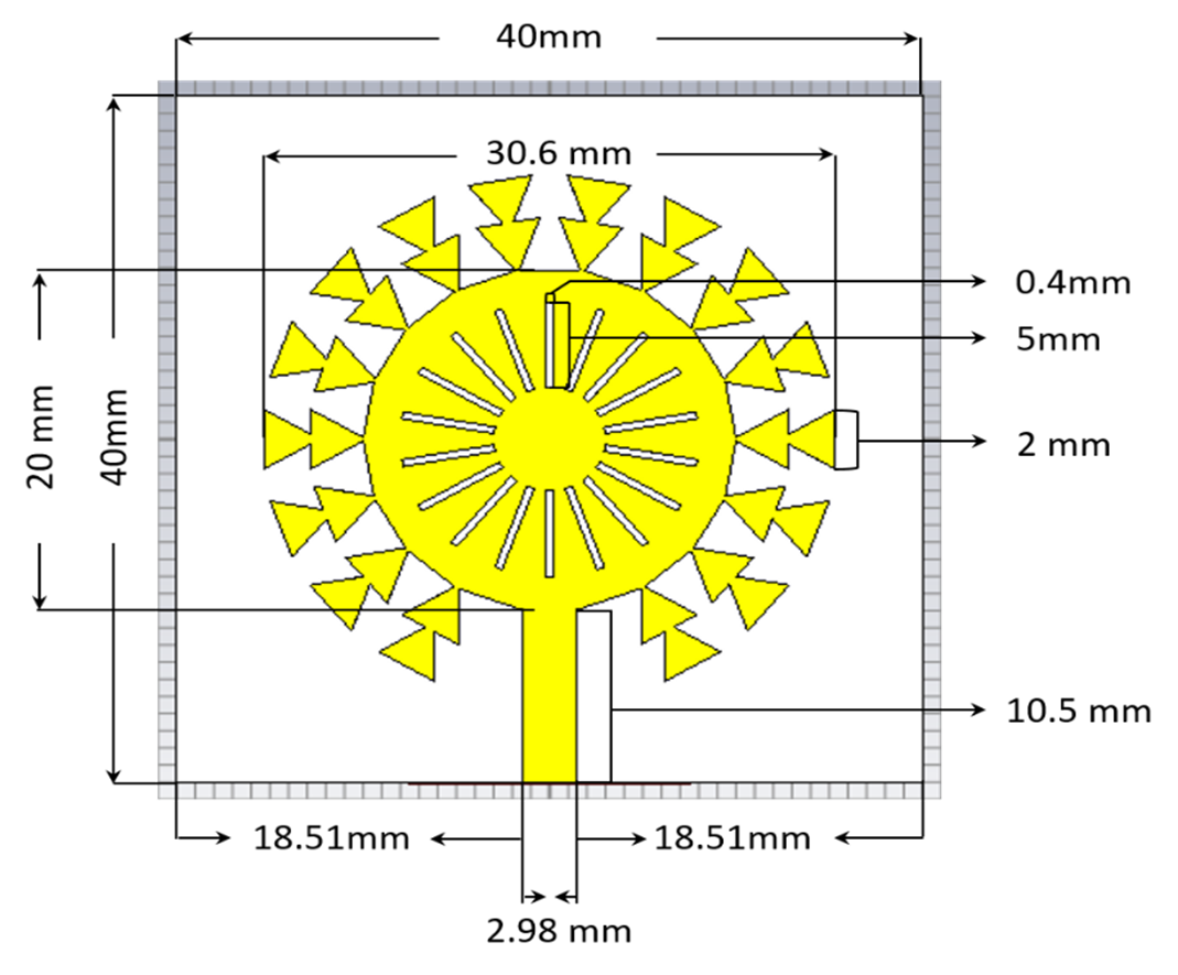
Fig:1 Antenna front view with dimensions in the early stages
In order to be used for multiband applications, the antenna is designed. Impedance matching, bandwidth, gain, and radiation efficiency are regarded as the most crucial characteristics throughout the designing process S11. The Rogers R03003 substrate, with a thickness of 0.8 mm and a dielectric permittivity of 3 (ℇr = 3), is used for the antenna’s design. 40 mm x 40 mm x 0.08 mm is the dimensions of the antenna ground plane. Two comparative antennas are constructed for this purpose. The corona virus shaped antenna’s initial geometric design is depicted in Fig. 1 (proposed). The values of each parameter for the first design are also displayed in the Fig. 1.
Antenna Design Process
As we considered creating a special antenna with outstanding features, the antenna design process included several optimization stages to improve its polarization and multiband properties.
In order to form a coronavirus shape, the antenna was initially built as depicted in Fig. 1 using CST simulation software. With a full ground, the antenna-1 (initial design) shows an average performance and low profile [8] bandwidths from 2 to 15 GHz which representing S11 and that is above -10 dB as shown in Fig. 2.
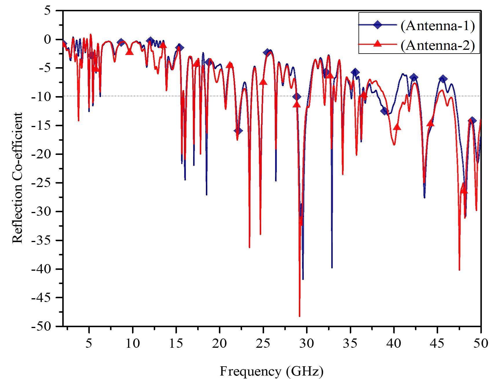
Fig. 2. Simulated S11 for the changes in patch side.
For further enhancement, we decided to make some adjustments to the antenna patch. The original antenna produced a patch of 18.10 mm × 4.80 mm × 0.08 mm next to each side of the transmission line (Fig. 3).
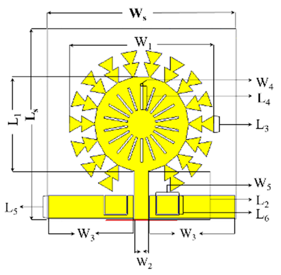
Fig. 3. The proposed antenna with the changes in patch side.
Table I shows the values of each parameter for the final design.
Table I Dimensions of the proposed antenna
| Parameters | Dimension (mm) | Parameters | Dimension (mm) |
| Ls | 40.00 | Ws | 40.00 |
| L1 | 20.00 | W1 | 30.6 |
| L2 | 10.5 | W2 | 2.98 |
| L3 | 2.00 | W3 | 18.1 |
| L4 | 5.00 | W4 | 0.4 |
| L5 | 4.8 | W5 | 5.00 |
| L6 | 4.00 | ||
| LG | 40.00 | WG | 40.00 |
With this, the modified antenna, subsidizes the lacking of the first ones. Getting additional bands is the major benefit of adopting the new rectangular patch. It has increased in bandwidth with high gain and also a resonant frequency is increased from 2 to 15 GHz.
As seen in Fig. 4, the planar patch antenna is made up of a dielectric substrate sandwiched between the ground layer and patch at the top and bottom, respectively. These linearly polarized Microstrip Patch Antennas have been designed for coronavirus structures by etching circles, triangles, rectangular, etc. on copper layers. In contrast to the bottom layer, which serves as the ground plane, the top patch layer serves as both a radiator and a receptor for antennas that send and receive signals.

Fig. 4. The lateral view of the proposed antenna
The designed antenna built 0.2 mm size of two insets in the new patch of the proposed antenna, on both sides of the transmission line where the patch dimension is 4.8 mm × 18.1 mm. So, the result that can be seen in Fig. 2 contains three more frequency resonances at 3800 MHz, 5000 MHz & 5500 MHz respectively. Regarding the initial antenna in Fig. 1, there are a total of 18 insets that have been inducted into the patch side of the patch antennas. Thus, the antenna attained 16 resonating frequencies at 15.7 GHz, 16 GHz, 17 GHz, 17.8 GHz, 18.5 GHz, 20.5 GHz, 22 GHz, 23.5 GHz, 24.7 GHz, 26.5 GHz, 29.5 GHz, 33 GHz, 34 GHz, 36.2 GHz, 36.7 GHz, and 43.5 GHz, as seen in Fig. 2 from -10dB to -45dB.
With the final modification, the proposed antenna has successfully achieved twenty-five multiband at 3.8 GHz, 5 GHz, 5.5 GHz, 15.7 GHz, 16 GHz, 17 GHz, 18 GHz, 18.5 GHz, 20.7 GHz, 22 GHz, 23.5 GHz, 24.7 GHz, 26.5 GHz, 29 GHz, 32 GHz, 33GHz, 33.5 GHz, 34.2 GHz, 35.7 GHz, 36.3 GHz, 36.7 GHz, 40 GHz, 42 GHz, 45.5 GHz and 47.5 GHz from -10dB to -50dB which are shown in Fig. 2.
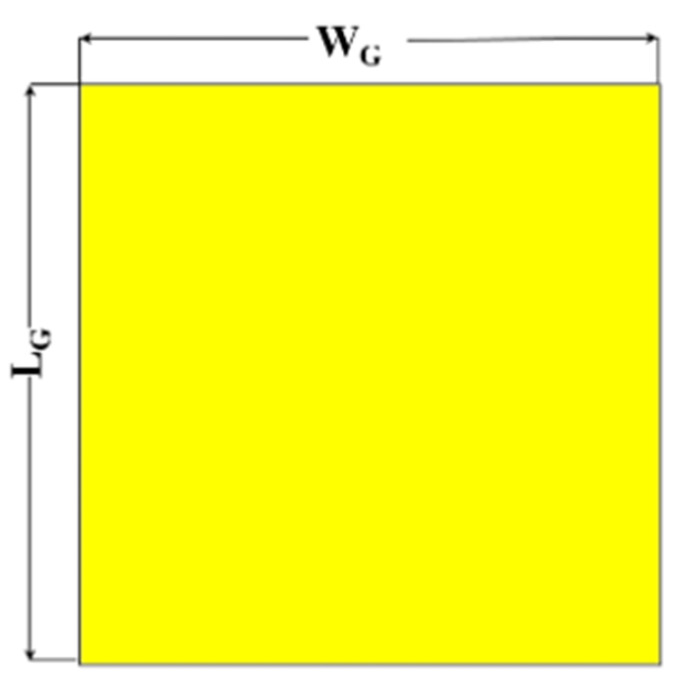
Fig. 5. The Back view of the proposed antenna (full copper ground)
Fig. 3 shows the final version of the planned coronavirus-shaped antenna, which has a full copper ground as shown in Fig. 5. A copper-made patch that measures 18.10 mm in width and 4.8 mm in length is installed on both sides of the transmission line. The patch is inserted by 0.2 mm, forming a rectangular structure that measures 5 mm by 4 mm.
Analysis of the Proposed Antenna’s Performance
The reference impedance [9] of the proposed antenna is 50Ω. It is just a factor which shows up initially in the definitions of the incident and the reflected wave. The following Fig. 6 and Fig. 7 show the efficiencies [10] and VSWR [11] of the proposed antenna at resonant frequencies.
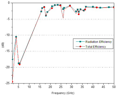
Fig. 6. Radiation Efficiency and Total Efficiency of the proposed antenna
VSWR is a measurement of the effectiveness of radio-frequency power transmission from a power source, through a transmission line, and into the patch antenna [12]. Here in this proposed antenna, a twenty-five resonating frequency band has been achieved.

Fig. 7(i). E-plane at 17.84 GHz
Every stage of the designed antenna has demonstrated a notable improvement. There are provided the cross-pol and co-pol radiation patterns.
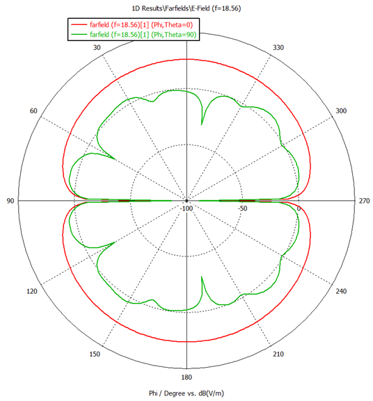
Fig. 7(ii). E-plane at 18.56 GHz
In “Fig. 7,” cross-polar and co-polar patterns are shown at resonance frequencies of 17.84GHz, 18.56GHz, 40.07GHz, and 47.56GHz, respectively. The cross-polar at phi 900 is shown in this diagram by the green line, while the co-polar is represented by the red line. Figures “Fig. 7(i)”, “Fig. 7(ii)”, “Fig. 7(iii)”, and “Fig. 7(iv)” show the proposed antenna’s robust resonance pattern at various resonant frequencies.
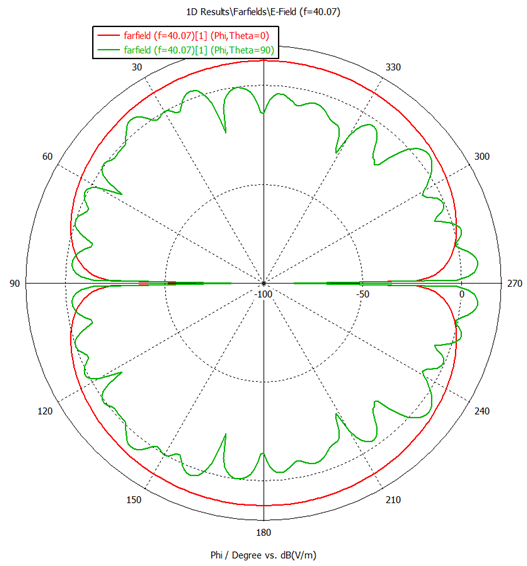
Fig. 7(iii). E-plane at 40.07 GHz
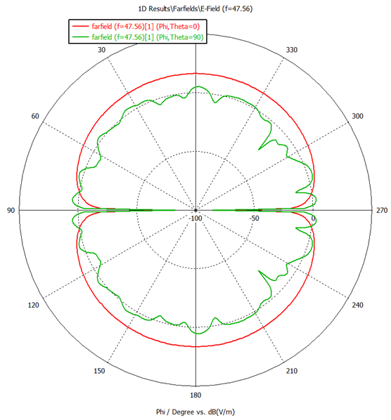
Fig. 7(iv). E-plane at 47.56 GHz
DISCUSSION & CONCLUSION
Discussion
Fig. 8. S-parameter of proposed antenna. The simulated result of the reflection coefficient has shown in Fig. 8. With high gain, S11 has been obtained in 25 distinct frequency bands between -10 dB and -50 dB. The achieved bandwidth are 140 MHz, 60 MHz, 80 MHz, 200 MHz, 310 MHz, 180 MHz, 200 MHz, 270 MHz, 260 MHz, 800 MHz, 610 MHz, 620 MHz, 220 MHz, 1630 MHz, 180 MHz, 250 MHz, 180 MHz, 300 MHz, 560 MHz, 440 MHz, 190 MHz, 2500 MHz, 420 MHz, 2300 MHz and 3400 MHz respectively. Fig. 7. illustrates the antenna’s radiation pattern in its polar configuration.
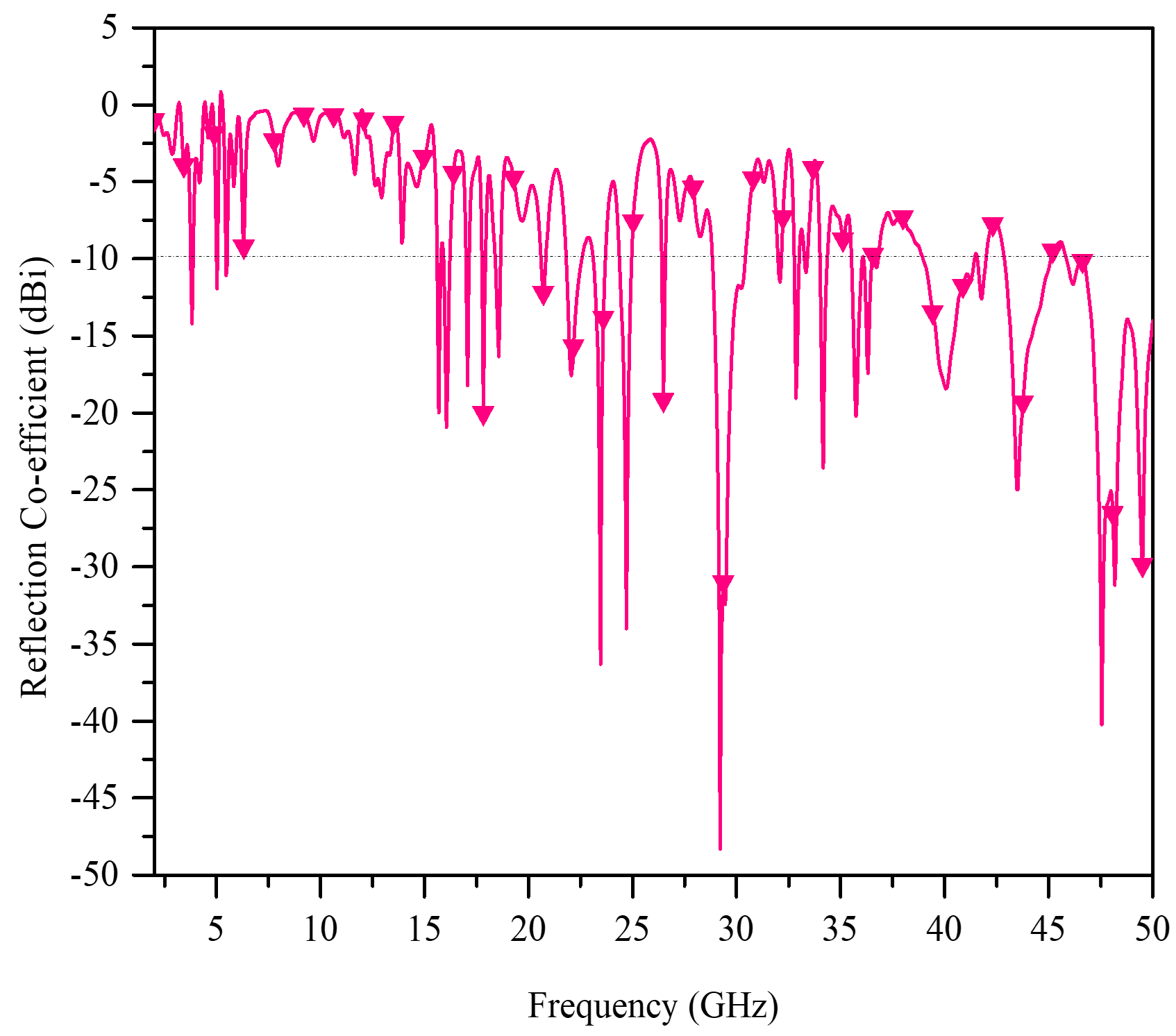
Fig. 8. S11 of proposed Antenna
The primary lobe direction at 0˚ in 36.7 GHz has a maximum gain of 12.7 dB.
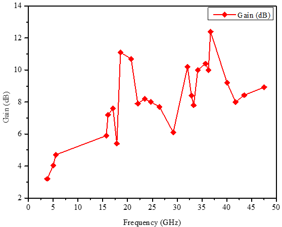
Fig. 7: Gain vs. Frequency graph of the proposed antenna
Table II A comparison between the proposed antenna and previous work
| Ref. | Size (mm2) | Antenna’s Type | Resonate Frequencies (GHz) | Max. Gain (dBi) |
| [13] | 28.5 × 34 | Sierpinski Carpet Fractal | 14.80, 17.92, 23.12, and 27.92 | 3.33 |
| [14] | 12 × 30 | Rectangular Shape | 23.9, 35.5, and 70.9 | 5.6 |
| [15] | 50 × 50 | Elliptical Patch Fractal | 2.6, 6 and 8.3 | 3.84 |
| This work | 40 × 40 | Corona Virus Shape | 3.8, 5, 5.5, 15.7, 16, 17, 18, 18.5, 20.7, 22, 23.5, 24.7, 26.5, 29, 32, 33, 33.5, 34.2, 35.7, 36.3, 36.7, 40, 42, 45.5 and 47.5 GHz | 12.7 |
Therefore, a Corona Virus fractal antenna with a dimension of 40 x 40 mm2 is proposed in this work to achieve size reduction. It may operate in 25 multiband simultaneously. Moreover, the suggested Corona Virus fractal antenna is smaller than other works, as depicted in Fig. 7 and Table III, and it has higher gain and more frequency bands than those other works. The suggested antenna also has wideband and narrowband capabilities.
Conclusion
A new coronavirus-shaped microstrip multiband patch antenna for VHF, UHF, L-band, and S-band applications has been designed and examined in this work. Superior multiband performance is effectively demonstrated by the suggested design, which has a maximum gain of 12.7 dBi at 36.7 GHz and covers 25 resonant frequencies. Compared to traditional designs, this antenna maintains good gain, impedance matching, and wide bandwidth coverage while achieving a compact form factor. The shape of the coronavirus was chosen for its engineering-driven optimization to improve electromagnetic performance, not just for its visual or conceptual originality. Additional resonant routes are introduced by the special shape, which enhances bandwidth efficiency and multiband behavior. The study demonstrates how structural changes affect antenna efficiency, polarization properties, and overall radiation performance through a steady refinement from the initial to final design stages. This flow ensures a systematic design evolution, reinforcing the shape’s technical advantage rather than its symbolic resemblance.
In the future, especially for 5G applications, we hope to increase the gain of the suggested antenna even more to boost signal intensity and coverage. Additionally, a comparison between simulation data and real-world outcomes will be done through experimental validation using measured performance analysis. With these improvements, the antenna will be able to be successfully incorporated into next-generation wireless communication technologies, offering a more affordable and high-performing option.
ACKNOWLEDGEMENT
This research was inspired by the COVID-19 pandemic, which reshaped global perspectives on innovation. The coronavirus-shaped antenna symbolizes resilience and scientific progress, showcasing how challenges drive advancements in wireless communication. We extend our sincere gratitude to the Faculty of Electrical and Electronic Engineering (EEE), Port City International University, for their invaluable resources and facilities, which were significant in completing this study.
REFERENCES
- C. A. Balanis, “Antenna Theory,” in Antenna Theory: Analysis and Design, New Jersey, Jhon Wiley & Sons, 2016, p. 1.
- CitizenChoice,”IN HISTORY OF 5G TELE-COMMUNICATION,” CitizenChoice, 2020. [Online]. Available: https://citizenchoicein/course/ emerging-technology-for-engineeringtheory/ Unit% 205/5g-tele-communication. [Accessed 2020].
- P.S.,.H.A.a.T.G. Riddhi Malik, “A Star Shaped Superwide band Fractal Antenna,” in 2018 3rd International Conference for Convergence in Technology (I2CT), Wakad Road, Pune, India, 2018.
- K.A.T.G.D.V.S.K.R.D. Vasujadevi M, “Fractal Antenna Design for Multiple Applications,” Innternational Journal of Engineering & Technology, Vaddeswaram, Guntur, Andhra Pradesh, India, 2018.
- J.C.Maxwell, “A Treatise on Electricity & Magnetism,” 3rd ed., New York, Dover Publications, Inc., vol.2, pp. 68-73.
- S. J. a. C. P. Bean, “Fine Particles, Thin Films and Exchange Anisotropy,” International Journal of Communications, Network and System Sciences, vol. 3, pp. 271-350, 1963.
- R. I. Apon, M. Z. Hossen, I. Das and S. Chakraborty, “Design and Performance Analysis of a CSRR Based Snowflake Fractal Antenna for Multiband Applications,” 5th International Conference on Electrical Information and Communication Technology (EICT), Khulna, 2021.
- Q.R.a.T.A.D. Gijo Augustin, “Low-Profile Antennas,” 2016.
- M. A. Cheremnykh, “REFERENCE IMPEDANCE SPECIMENS WITH A FREQUENCY INDEPENDENT SWR IN RECTANGULAR WAVEGUIDES,” pp. Meas Tech 10, 699–703, June 1967.
- M. M. U. R. L. C. P. A. K. S. Makhluk H. Prio, “Total efficiency comparison of different shaped microstrip patch antennas having Defected Ground Structure,” 1st International Conference on Electrical & Electronic Engineering (ICEEE), RUET, Rajshahi, Bangladesh, 2015.
- S. I. Tous, “Voltage Standing Wave Ratio,” 2010.
- A. Synak, “ERASMUS STUDENT EXCHANGE PROJECT: DESIGN AND IMPLEMENTATION OF UHF PATCH ANTENNA,” Universitat Politècnica de Catalunya, 19 June 2014. [Online]. Available: http://hdl.handle.net/2099.1/21993. [Accessed 2019].
- M. S. Maharana, G. P. Mishra and B. B. Mangaraj, “Design and simulation of a Sierpinski carpet fractal antenna for 5G commercial applications,” International Conference on Wireless Communications, Signal Processing and Networking (WiSPNET), Chennai, India, 2017.
- S. B. Sarkar, “Design and analysis of 5.2 GHz fractal rectangular microstrip patch antenna using Hilbert curve,” International Conference on Wireless Communications, Signal Processing and Networking (WiSPNET), Chennai, India, 2017.
- A. K. a. P. K. Malik, “Multiband Elliptical Patch Fractal and Defected Ground Structures,” Progress In Electromagnetics Research B, Vol. 91, pp. 157-173, 2021.