
Design and Implementation of a Homemade Remote Control and Obstacles Avoidable Fire Extinguisher Robot
- Md. Shahnuaz Khan
- Juwel Das
- Md. Ismail Haque
- Md. Eftekhar Alam
- Md. Lokman Hossain
- 255-263
- Nov 17, 2023
- Health And Cybersecurity
Design and Implementation of a Homemade Remote Control and Obstacles Avoidable Fire Extinguisher Robot
Md. Shahnuaz Khan, Juwel Das, Md. Ismail Haque, Md. Eftekhar Alam, Md. Lokman Hossain
Electrical and Electronic Engineering, International Islamic University Chittagong Chittagong, Bangladesh
DOI: https://doi.org/10.51244/IJRSI.2023.101025
Received: 11 May 2023; Revised: 20 August 2023; Accepted: 29 August 2023; Published: 17 November 2023
ABSTRACT
The aim of this project is to develop a fire extinguisher robot and its operation is controlled by using IR remote. This robot is loaded with the tanker and a pump and sprinkles water to fire. It is a micro controller based robot. The robot can automatically sense and overcome obstacles on its path. It has the ability to detect any flame. At the transmitting end using push buttons, commands are sent to the receiver to control the movement of the robot. We can use this robot to fight against fire and to minimize the losses. The robot is used to fight the fire where the humans cannot enter. This can be kept in industry, office, home for the safety against fire. The robot can show the actual situation by using a wireless camera.
Index Terms: Artificial Intelligence, Autonomous Mobile Robot, Flame Sensor, Buzzer Module
INTRODUCTION
The word “robot” comes from the Czech word “robota,” which denotes forced labor or work. The robot was created to perform some chores. While many tasks are difficult for humans to complete, many are simple for robots. Robots are increasingly present in human lives. Robots are made of a combination of programming, mechanical, and electronics (non- programmable in some cases). Robot uses its sensors to sense its surroundings, analyze that information, and take action. Here, we’ve created a remote-control, obstacle-detecting fire extinguisher robot that will detect fire and alert us to a fire. To move the robot close to the flame and spray water on it, we maneuver the robot using a remote control so that we can hear the warning. Human life depends on the safety of the marketplace, the house, the laboratory, the office, the factory, and the structure. We have created several different kinds of fire security systems, each of which includes a sensor-equipped fire protection robot. The fire security system can identify unusual and hazardous circumstances and alert us. For the intelligent building, we first create a fire defense robot with an extinguisher. Also, because they are difficult to reach, electrical equipment can inflict minor burns that are difficult for humans to notice. Yet a robot can easily get there. How long it takes the user to put out the fire. Finding a supply of water to put out a fire may take a long time for the user. In a confined space that is difficult for the user to access, the fire is difficult to detect. Yet a robot can easily get there. The paper’s goals are to build a robot-car with the following characteristics –
- To design a robot car for sense the flame of fire and give us security alarm.
- To design a robot car for seeing the movement of robot and actual situation by using a wireless camera.
- To design a robot car for avoiding obstacles and spray water on the fire from a long distance
The robot in figure 1 moves in all directions from its mount point with the help of two sensors. The robot motion will automatically halt and alert the presence of fire when a flame or high temperature point is detected. The computer terminal then turns on the fire suppression system after receiving the sensor signals. It determines the precise compass direction of the fire. It can sense more precisely while being more flexible [1]- [7].
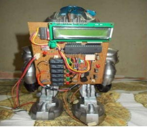
Figure 1: Artificial Intelligence Fire Fighting Robot [1].
Figure 2 depicts a rotating robot that is actively searching for fire. Sensors affixed to the slides carry out this scanning. It advances in the direction of the fire when one is detected, stops 30 cm in front of it, and activates the extinguisher to put the fire out. The Arduino Leonardo board is utilized in this project. Every Arduino board is an option. For this project, a Keyes flame sensor module with a sensitivity adjustment pot is used. It has a positive supply pin that requires a +5 V supply. Pin GND has to be grounded. This module offers outputs that are both digital and analog. In this project, only digital output is utilized [2].
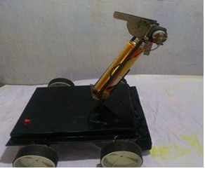
Figure 2: Autonomous Fire Fighter Robot [2].
This project, which is represented in Figure 3, was created as a mobile robot that can be trained and controlled to do multiple tasks autonomously. The robot learns the fundamentals of navigation as well as how to spot and put out fires. A microcontroller PlC16F84A is used to manage this robot, and RC circuits are used to support it and act as drivers for DC motors and other electronic parts. This robot has an expandable and retractable fire sensor, enabling it to detect fires, react to them, and control water pump systems. This robot also has a battery monitoring circuit, which makes it simpler to keep track of the battery life. It can also keep a track in different communication systems [8]– [21].
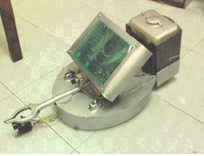
Figure 3: Autonomous Mobile Robot [3].
SYSTEM DESIGN
There are multiple phases in this project to operate it. In Figure 4, a block diagram is displayed. The sensor and input/output devices will be managed by a microcontroller unit. The circuit will be powered by a source of 6 V. There will be a flame sensor that will act as the input device in this situation. The flame sensor will alarm and let us know when it spots a flame. Four gear motors will be utilized to control the robot’s mobility, and a motor controller driver will be in charge of those motors. The microcontroller unit will be connected to the driver for the motor controller. With a relay module attached to the microcontroller, an air pump motor will have been employed to put out the fire. The movement of the robot, the alarm, and the pump are all controlled by an IR remote. In order to avoid any obstacles in front of it, an ultrasonic sensor is also utilized. Robot movement is observed using a wireless camera.
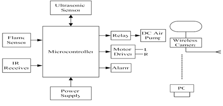
Figure 4: Block diagram of Fire extinguisher Robot.
Diagram of a fire extinguisher’s circuit as shown in figure 5, a robot. The IR receiver is attached to the microcontroller’s 4 no pin, and the flame sensor is connected to its 7 no pin. Power supply is connected to the microcontroller’s 20-pin header. Pins 13, 14, and the ultrasonic sensor are linked to the microcontroller. The motor driver is attached to the microcontroller’s 15, 16, 17, and 18 no-pins, while the alarm is connected to the no. 12 pin. The microcontroller’s pin number 11 is where the 5 V relay module is connected. When this relay is turned on by the microcontroller, it turns on the air pump motor.
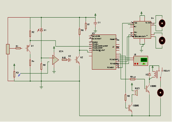
Figure 5: Circuit diagram of Fire extinguisher Robot
If the microcontroller receives a signal from the IR receiver, it will begin to function according to that signal. The signal is wirelessly transmitted to the microcontroller. Protocol is required for wireless communication. We employ RC5 protocol (Phillips). To function, the RC5 protocol requires a few specialized circuits. The IR receiver and the microcontroller are incompatible with one another. So, using programming, we link the IR receiver and microcontroller. When an IR signal is received, the IR receiver’s output changes from being active high to active low. Nonetheless, we write programs for active high microcontrollers. If we like, we may also write programs for active low microcontrollers, although doing so makes the programs more complex. In order to invert the output of the IR receiver, we therefore do not modify the program to active low but rather utilize a pnp transistor as an inverter. The emitter of the transistor is connected to the positive voltage, the collector is pulled down by a resistor, and the output of the IR receiver is connected to the transistor’s base. We receive voltage on the collector if the base is low; otherwise, we do not. The pull down resistor is low when the transistor is off, and it is high when the transistor is on. Now, we can quickly obtain the active high from the IR receiver’s output. Programming is used to link the IR receiver and the microcontroller. The output of the flame sensor is continuously monitored by the microcontroller (photo diode). An operational amplifier is linked to the flame sensor’s output. The operational amplifier serves as a voltage comparator in this instance. We supply operational amplifier’s inverting input with 5 V of reference voltage. By doing this, we can modify the flame sensor’s sensitivity. Both the minority carrier and the reverse current are at their lowest when there is no flame on the flame sensor. Hence, there won’t be any current flowing inside the flame sensor (roughly). When the reference voltage is high then IR output is also high so the LED will on then with this transistor will on and the microcontroller pin RA5 get low voltage. That means there is no fire. When there is flame on the flame sensor then the reverse current is increased for minority carrier. So current will flow inside the flame sensor. When the reference voltage is low then IR output is also low so the LED will off then with this transistor will off and the microcontroller pin RA5 get high voltage. That means there is fire and it on the alarm. To avoid any obstacles in front of it, we have utilized an ultrasonic sensor, model number SR04. Because the electricity line gets cut off during a fire. We are able to control the robot’s movement in the dark and in the presence of smoke. The ultrasonic sensor has a 50 cm range. If there are no obstacles within 50 cm, it advances. But, if it encounters an obstruction within 50 cm, it will stop and begin to beep. Light is not needed for ultrasonic to function. A wireless camera was also mounted outside the circuit so we could see how the robot moved at night. We utilize four dc motors to power the robot automobile. We utilize an L293D motor driver IC to connect these motors to the microcontroller. It has integrated dual H-bridge motor drivers (IC). A and B are them. The robot car will travel left and right when A and B are in the forward position, backward when A and B are in the forward position, and backward when A and B are in the reverse position. We utilize an air compressor to spray water, and the air compressor is connected to a water reserver, which is connected to a spray. The water will automatically spray when the water reserver’s pressure is raised. We utilize a relay that is coupled to a transistor to turn the pump on and off. The microcontroller’s first pin, designated MCLR, is a current-limiting resistor. The first pin of the microcontroller is always kept high because it is advised by the manufacturer. However, maintaining the top pin has a requirement. That is, a resistor must be used to make the No. 1 pin high. We utilize a 100 µF capacitor to ensure that the supply is stable.
IMPLEMENTATION AND RESULTS
This section demonstrates how the practical interfacing is implemented in full, step-by-step detail. The circuit and its operation are explained in detail in the overview. Figure 6 in the section below provides a thorough description of the project.
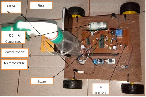
Figure 6: Overview of the project
Flame sensor is connected with the 7 no pin of micro controller (RA5).
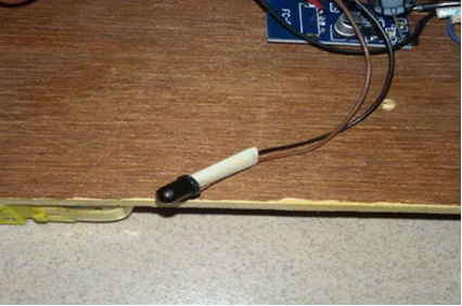
Figure 7: Flame Sensor
A relay module is used to run the Air pump and which is connected to the pin no 11 of microcontroller. It is used to on/off the pump.
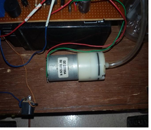
Figure 8: Air Pump
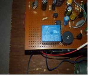
Figure 9: Relay
Buzzer is connected to the pin 12 no of of microcontroller. It is used to sound a alarm when any sensor is activated.
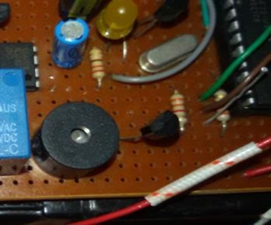
Figure 10: Buzzer
Cost Analysis is shown in table I.
| Components | Unit | Price (BDT) |
| Gear Motor (5v) | 4 | 600 |
| Wheel | 4 | 100 |
| Mini Air Compressor (6v) | 1 | 800 |
| Battery 6V(Rechargeable) | 1 | 500 |
| IR Remote | 1 | 300 |
| IR Receiver | 1 | 20 |
| Photo Diode | 1 | 5 |
| Operational Amplifier (LM358) | 1 | 20 |
| Microcontroller (PIC16F72) | 1 | 150 |
| Crystal Oscillator (4MHz) | 1 | 20 |
| Voltage Regulator (5v) | 1 | 20 |
| Motor Driver (L329D) | 1 | 100 |
| Transistor | 4 | 50 |
| Board | 1 | 100 |
| Zener Diode (2.5v) | 1 | 10 |
| Variable Resistor (5K) | 1 | 50 |
| LED | 1 | 12 |
| Buzzer | 1 | 40 |
| Relay (5v) | 1 | 60 |
| Capacitor | 3 | 25 |
| Resistor | 10 | 10 |
| Ultrasonic Sensor (SR04) | 1 | 200 |
| Boost Converter | 1 | 250 |
| Wires | 80 | |
| Total | 3,612 |
To boost the water flow, a tiny air compressor has been used. When it discovers any barriers in its path, its intelligence may decide what to do. We watched the robot’s movements with a wireless camera. Spraying the water simulates the water’s flow. The practical overview of our project, including the flame sensor, relay, air pump, and buzzer, is shown below. A table detailing the cost analysis of the components is also provided.
CONCLUSION AND FUTURE WORK
A robot is an artificial agent that is virtual or mechanical. In reality, it’s typically an electro-mechanical device that can perform activities on its own thanks to electronic or computer programming. Another common trait is that robots frequently give the impression of having agency or intent by their look or behaviors. The project is carried out with meticulous circuit design and assembly under strict supervision. The hardest part of the project was synchronizing the input and output, but with much drive and effort, it can now be completed successfully. The effectiveness of the suggested method for both industrial and security purposes has been confirmed.
Future Works:
- The project has been motivated by the desire to design a system that can detect fires and take appropriate action, without any human intervention.
- Refill/ Replacement of water tank of fire extinguisher robot.
- It can be used in several rooms.
- GSM module can be used for giving alert.
- Fire-fighting is an obvious candidate for such automation.
REFERENCES
- Kristi Kosasih, E. Merry Sartika, M. Jimmy Hasugian, dalMuliady, “The Artificial Intelligent Fire Fighting Robot”, Electrical Emgineering Journal Vol. 1, No. 1, October 2010.
- Sunil Mathew, Gaikwad Sushanth, KR Vishnu, V. Vishnu Nair, and G. Vinoth Kumar,“Autonomous Fire Fighter Robot”, International Journal of Innovation and Scientific Research Vol. 22 No. 2 Apr. 2016.
- Md Hafizul Hasmie Md Suhaimi, “Autonomous Mobile Robot: Recognize & Response to Fire”, Universiti Tun Hussien Onn Malaysia (UTHM), Malaysia, 2007.
- Mazzidi, “8051 Microcontroller and Embedded Systems”, Prentice Hall Publications, 2nd Edition, 2005.
- Ajay V Deshmukh, McGraw-Hill, “Microcontrollers Theory and Applications”, Tata McGraw-hill Publishing Company Limited, New Delhi, 2005
- C. Shaohua, B. Hong, Z. Xianyun, and Y. Yimin, “A fire detecting method based on multi-sensor data fusion,” in Systems, Man and Cybernetics, 2003. IEEE International Conference on, 2003, pp.3775-3780 vol.4.
- Kriti Bhagat, S. Deshmukh, Sharaddha Dhonde, Sneha Ghag, “Obstacle Avoidance Robot”, International Journal of Science Engineering and Technology Research (IJSERT), Vol-5, Issue- 2, February, 2016.
- Ratnesh Malik, “Fire Fighting Robot: An Approach”, Indian Streams Research Journal Vol.2, Issue. I/March; 12 pp.1-4
- Lakshay Arora, Prof.Amol Joglekar, “Cell Phone Controlled Robot with Fire Detection Sensors”, (IJCSIT) International Journal of Computer Science and Information Technologies, Vol. 6 (3), 2015, 2954-2958.
- K. L. Su, “Automatic Fire Detection System Using Adaptive Fusion Algorithm for Fire Fighting Robot,” in Systems, Man and Cybernetics, 2006. SMC ’06. IEEE International Conference on, 2006, pp. 966-971.
- Microcontroller Cookbook PIC & 8051, Second Edition, Mike James, Newnes, Reed Educational and Professional Publishing Ltd, Jordan Hill, Oxford, United Kingdom, 2001.
- “L293D Motor Driver IC | L293D Datasheet”, Engineersgarage.com, 2017. [Online]. Available: https://www.engineersgarage.com/electronic-components/l293d-motor-driver- ic.
- Available: https://www.techshopbd.com/productcategories/motors/1101/gear-motor-techshop-bangladesh [2017].
- Available: http://tinkbox.ph/sites/tinkbox.ph/files/downloads/5V_BUZZER_MODULE.pdf.
- M. I. Haque, R. Yamada, J. Shi, J. Wang, D. Anzai, “Channel Characteristics and Link Budget Analysis for 10-60 MHz Band Implant Communication”, IEICE Transactions on Communications, Apr. 2021, Vol. E 104-B, No.4,410-418.
- M. I. Haque, J. Wang, D. Anzai, “Path Loss and Group Delay Analysis at 10-60 MHz Human Body Communication Band”, IEICE Technical Report, EMCJ2019-78,13th Dec 2019,19-22.
- M. I. Haque, K. Yoshibayashi, J. Wang, G. Fischer, J. Kirchner, “Design and Evaluation of Directional Antenna for Shoe-mounted Sensor for Position Identification of Elderly Wanderer”, Sensing and Bio-Sensing Research, Elsevier, Volume 34, December 2021, 100451 (doi: 10.1016/j.sbsr.2021.100451).
- M. I. Haque, K. Yoshibayashi, J. Wang, G. Fischer, J. Kirchner, “Directive Antenna Design at 2.4 GHz on Foot Surface for Wanderer Location Identification”, 2020 International Symposium on Antennas and Propagation (ISAP), January 25-28, 2021, Osaka, Japan, 635-636.
- M. I. Haque, R. Yamamoto, J. Wang and K. -I. Kakimoto, “Measurement Performance of NKN Piezo Material for Powering Shoe-mounted Sensor,” 2022 International Conference on Innovations in Science, Engineering and Technology (ICISET), 2022, pp. 324-328, doi: 10.1109/ICISET54810.2022. 9775861.
- S. A. H. Chowdhury, M. S. Anower, J. E. Giti, M. I. Haque, “Effect of signal strength on different parameters of cross- correlation function in underwater network cardinality estimation”, ICCIT, Dhaka, 22-23 Dec 2014
- M. S. Anower, S. A. H. Chowdhury, J. E. Giti, A. S. M. Sayem, M. I. Haque, “Effect of bandwidth in cross-correlation based underwater network size estimation”, ICECE, 20-22 Dec, 2014.