Electrical Ground Fault Monitoring System Utilizing Arduino and Android Application
- Dennis Sarinas Tibe
- 562-569
- Jul 22, 2024
- Engineering
Electrical Ground Fault Monitoring System Utilizing Arduino and Android Application
Dennis Sarinas Tibe
Leyte Normal University, Philippines
DOI: https://doi.org/10.51244/IJRSI.2024.1106043
Received: 28 May 2024; Revised: 13 June 2024; Accepted: 18 June 2024; Published: 21 July 2024
ABSTRACT
The increasing incidence of residential fires caused by electrical ground faults worldwide challenges researchers to develop systems capable of mitigating their occurrence. The absence of periodic equipment maintenance and monitoring facilities leads to potential electrical hazards to humans and properties. Technological advances have made online electrical ground fault monitoring equipment possible, allowing users to remotely access information about the operational condition of electrical equipment in their homes. This paper presents the development and testing of an Electrical Ground Fault Monitoring System using Arduino with an Android Application (EGFMSAAA). The system integrates an Electrical Ground Fault Detector Device (EGFDD) with an Arduino GSM Shield to detect and transmit electrical ground fault parameters. It also includes an Android-based application for real-time monitoring and control. The system was tested for accuracy and reliability, demonstrating its capability to detect faults, provide early warnings, and allow users to take preventive measures remotely. The findings indicate that the EGFMSAAA effectively enhances safety and reduces the risk of electrical fires in residential settings.
Keywords: Ground Fault, Online Monitoring, Equipment Grounding, Microcontroller, GSM, and Android
INTRODUCTION
Past and present researchers are still developing more accurate and faster electricity data acquisition and monitoring via wireless transmissions. Energy consumption, losses, pilferages, and other electrical parameters are monitored via GSM-based technology to establish a more reliable, accurate, and safe system operation.
Approximately 25,900 electrical fires in residential buildings were reported to fire departments in the United States each year. These fires caused 280 deaths, 1,125 injuries, and $1.1 billion in property loss (Topical Fire Report Volume 21, Issue 8 Series, 2019). National Fire Protection Agency (NFPA) and National Association of State Fire Marshals (NASFM) reported that 50 to 75 percent of electrical home fires in the United States have arc fault conditions (Siemens Industry, Inc., 2020). The report calls for an immediate response to monitor the occurrence of an electrical equipment ground fault. However, online monitoring is necessary to provide early warning signs and alert the personnel of the potential hazards it could bring.
Solar America Board for Codes and Standards (2015) introduces a mitigation method for electrical ground fault monitoring at a level sufficient to determine if equipment integrity has degraded and unscheduled maintenance is required. But nowadays, the exciting Android mobile application development and modularized hardware design make real-time ground fault monitoring possible and more accessible to implement. It will enable an innovative mobile application for data acquisition that facilitates mobile users’ awareness of ground fault issues.
It developed an Electrical Ground Fault Monitoring System to provide an online information system and address electrical events causing fire hazards, property loss, personnel death, and injuries. The development incorporates equipment ground fault detection and real-time data acquisition subsystem. It allows the user to constantly monitor and carry out information on the operational profile or preventive measures on electrical equipment. The system utilizes a GSM-based application; therefore, users can take advantage of the remote monitoring and control capability anytime and anywhere. On the contrary, since it is a mobile-based technology, the system’s operation is still dependent on the availability and operational condition of the network provider.
The Electrical Ground Fault Monitoring System integrates developed subsystems using Arduino and Android Applications, the Electrical Ground Fault Detector Device (EGFDD) using Arduino with shield, and the Electrical Ground Fault Monitoring System (EGFDD). The EGFDD contains a power analyzer that measures and reads electrical properties such as voltage, current, and power drawn by faulted equipment. In contrast, the EGFDD is a mobile application that serves as a monitoring system.
Objectives:
This study aims to develop an Electrical Ground Fault Monitoring System using Arduino with Android Application with the following specific objectives:
- Develop an Electrical Ground Fault Detector Device (EGFDD) with Arduino GSM Shield capable of detecting and transmitting equipment ground fault information.
- Develop Android-based Electrical Ground Fault Monitoring System (ABEGFMS) software for mobile applications.
MATERIALS AND METHODS:
The development of EGFMS includes the development of EGFDD with Arduino GSM Shield and ABGFMS, and it follows the methodological approach. The procedure consists of determining the specification of system requirements, architectural design, software development, integration, and testing.
The electrical readings obtained, the degree of accuracy by a standard measuring instrument, and the measured electrical parameters sensed by GFDD corresponding to the electrical load applied are compared and tested. Then, the developed EGFMS must respond to its intended functionality requirement based on the designed graphical user interface.
System Requirement
As to the system’s acceptability, it must respond to some electrical safety requirements imposed by regulating standards for personnel and equipment. Online monitoring of signal detection and data transmission from the equipment grounding conductor achieves system requirements. Online ground fault monitoring is done through current, voltage, and power transmission to the mobile user with equipment grounding conductor connected to earth ground.
The system must provide early warning signs for equipment ground fault. Thermal Management Solution stated that a Ground-Fault Equipment Protection Device (GFEPD) typically has a trip level of 30mA. The equipment protects equipment from damage due to overheating or fire. Therefore, an electrical ground fault below 30mA will serve as an alert level for detection to protect equipment against thermal damage before it can create fires. 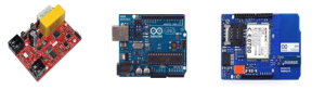
- AC Power Analyzer b. Arduino Uno MCU Arduino GSM Shield
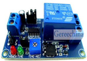
2. OptoIsolated Switch Module
Figure 1: Ground Fault Detector Device Components
All signals detected coming out from the equipment are in analog form. AC power analyzer detects electrical parameters and processes the analog data into a digital format that Arduino Uno Microcontroller can understand. The microcontroller is equipped with UART to communicate with the AC Power Analyzer through Rx and Tx terminals. The Arduino GSM shield is interfaced with the microcontroller to transfer digital signals and vice versa through Rx and Tx. A 5-volt DC supply powers all modules. Embedded system software is being developed and loaded to the microcontroller to handle tasks for data transferring and formatting and also to provide control action remotely. The microcontroller established a baud rate setup to allow proper data transmission.
Software Development
The system requires the development of Microcontroller Embedded System Software and an Electrical Ground Fault Monitoring System (EGFMS) mobile application. The program loaded to the microcontroller will serve its logical function of controlling and communicating with all the components. On the other hand, the mobile application will cater to graphical user interfaces to provide monitoring and control capabilities. The user can also personalize the mode of the functionality of the mobile for convenience.
Microcontroller Embedded System Software
The Arduino Uno Microcontroller handles and manipulates incoming and outgoing signals. This system performs tasks such as manipulating ground fault detected signals into an understandable format by other interfacing modules, sending them to the mobile application, and initiating control of electrical equipment if necessary. The control program flow chart shown in Figure 3 is the microcontroller’s algorithm. The microcontroller will receive signals from the power analyzer depending on the functionality mode dictated by the mobile application. The microcontroller manipulates the received signals accordingly through a compiled set of instructions—the manipulated data corresponds with the received signals from the power analyzer in the GSM module. The registered data transmitted is now in the Electrical Ground Fault Monitoring System mobile application. In the control aspect, the microcontroller will receive a control command from the mobile application to shut down electrical equipment. The microcontroller used C programming language.
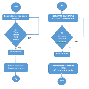
Figure 2: Program Flow Chart
Android-Based Ground Fault Monitoring System
The ABGFMS mobile application contains a graphical user interface that provides the functionality shown in Figure 4. The application will start upon pressing the Start Application button, telling the microcontroller to send data. The Real-Time Data button contains present and historical data. The data is a text message corresponding to the detected fault signal and warning indicators. The user can customize the data reception depending on how often he wants to receive information. There is also an option to de-energize the equipment remotely by pressing the Shutdown Equipment button if an extreme event occurs. The device will stop the equipment’s operation, isolating it from the supply line. The end application informs the microcontroller to stop sending data, and the above statements will be the source code reference when developing the mobile application. The MIT App Inventor used the coded application’s design, layout, and functionality.
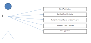
Figure 3: Application Functions
Integration and Testing
To verify each component’s intended functionality and data are in proper output, each test before integrating other components. The system undergoes a top-down testing strategy to immediately fix bugs and errors between hardware and software. Every element is interfaced and interplayed with the controlling subsystem (Arduino Uno microcontroller) step by step. Interfacing between the power analyzer and the microcontroller was done first to obtain the electrical quantity readings of the load utilizing the Arduino monitor. Next, the Arduino GSM shield ensures the mobile application receives the message. Finally, a switching command is sent to the microcontroller from the mobile application to enable the magnetic contactor to change its state.
RESULTS AND DISCUSSIONS
Application of the System to Electrical Equipment
A standard electrical convenience outlet with three-prong terminals (live, neutral, and ground) connects electrical equipment terminals. Only live and neutral conductors expect to carry current during regular operation once the electrical load energizes. The ground conductor carries current only when an equipment ground fault occurs, considering that the equipment grounding conductor connects to the earth’s ground. Therefore, a complete circuit between the equipment grounding conductor at ground fault conditions. Since the neutral conductor connects to the earth’s ground in a grounded neutral system, the neutral is always at the potential ground. The system utilized the live and equipment grounding terminals to detect ground fault electrical parameters.
Ground Fault Detector Device
In the method section, the components associated with EGFDD. The developed device has two inputs and two output terminals, connecting the equipment’s live and grounding terminals. As reflected in Figure 1, the conductor from the magnetic starter connects to the two input terminals of the EGFDD. Meanwhile, the conductors running from the output terminals of EGFDD connect to the live and equipment grounding terminal. Therefore, the two input terminals are labeled live and ground, and the two output terminals are labeled similarly to the input terminals. It also has one pair of control terminals for triggering the magnetic switch.
Android-Based Ground Fault Monitoring System
Data Transmission
The simulation of the various electrical loads with the EGFDD and the ABEGFMS interface, as shown in Figure 5, meets the system requirement mentioned above and validates its intended functionality—the simulation in the same manner as the above discussion on GFDD terminal assignments. The GFDD transmits current, voltage, and power drawn by the load by connecting its input terminal to the AC source and output terminal to the load with its ground terminal connected to earth ground. It also informs the user of the operating condition of the equipment.
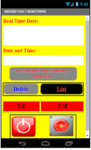
Figure 4: ABGFMS Graphical User Interface
As expected output, the ABGFMS received electrical data during the simulation using various electrical load readings, as shown in Table 1. Electrical loading changed to check if the program responded correctly to the change of electrical signals. As it appears on the table, it is evident that the developed system acts according to the specification requirements stated.
In normal running conditions, the voltage transmitted by the GFDD is ideally equal to the supply voltage, and the current is always equal to zero. Under load conditions, a zero current reading implies that a ground fault does not exist; Otherwise, a non-zero current reading indicates an electric current flowing at the equipment grounding conductor and is at ground fault condition.
Table 1: Transmitted Signal with Grounded Equipment Grounding Conductor
| Electrical Loads | Transmitted Data | |||
| Current (amperes) | Voltage (volts) | Power (watts) | Equipment Condition | |
| No load | 0 | 232.34 | 0 | Normal |
| 1- 3W LED bulb | 0.01 | 232.18 | 13.93 | Ground Fault Occurs (Shutdown Equipment) |
| 1 x 5W LED bulb | 0.02 | 231.79 | 27.81 | Heating Starts (Shutdown Equipment) |
| 1 x 7W LED bulb | 0.03 | 231.92 | 60.30 | Overheating (Shutdown Equipment) |
| Electric Fan | 0.26 | 232.19 | 74.30 | Overheating |
Data Transmission Time Interval
Figure 6 reflects the user interface of ABGFMS under the Customize Transmission Interval button. When pressed, the button sent a message requesting the EGFDD to send data with an interval indicated. A sent message request will prompt and appear on the screen.
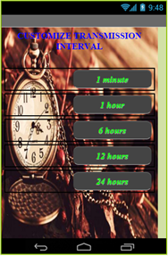
Figure 5: Customize Transmission Interval Interface
Table 2 shows the real-time monitored data transferred by GFDD with an indicated date and time. The system expects to transmit data per the requested time interval of data transfer. As you will notice, there is a considerable delay in the time interval in data reception since the system is greatly dependent on the operating condition of the network provider. The change in the sent information corresponds to the change in the electrical load setup.
Table 2: Real-Time Monitored Data
| Data Transfer Interval | Sent Information | Date and Time |
| 1 minute | Ground Fault Occurs (Shutdown Equipment) | 08/17/2023 12:33:01 PM |
| Heating Starts (Shutdown Equipment) | 08/17/2023 12:35:15 PM | |
| Overheating (Shutdown Equipment) | 08/17/2023 12:36:40 PM | |
| 1 hour | Ground Fault Occurs (Shutdown Equipment) | 08/17/2023 01:40:24 PM |
| Heating Starts (Shutdown Equipment) | 08/17/2023 02:43:05 PM | |
| Overheating (Shutdown Equipment) | 08/17/2023 03:44:58 PM | |
| 6 hours | Ground Fault Occurs (Shutdown Equipment) | 08/17/2023 09:49:44 PM |
| Heating Starts (Shutdown Equipment) | 08/18/2023 03:51:02 AM | |
| Overheating (Shutdown Equipment) | 08/18/2023 09:54:38 AM | |
| 12 hours | Ground Fault Occurs (Shutdown Equipment) | 08/18/2023 09:55:44 PM |
| Heating Starts (Shutdown Equipment) | 08/19/2023 09:57:02 AM | |
| Overheating (Shutdown Equipment) | 08/19/2023 09:58:38 PM | |
| 24 hours | Ground Fault Occurs (Shutdown Equipment) | 08/20/2023 10:01:28 PM |
| Heating Starts (Shutdown Equipment) | 08/21/2023 10:02:57 PM | |
| Overheating (Shutdown Equipment) | 08/22/2023 10:04:12 PM |
Controlling Data Transmission and Equipment Operation
Data transmission and equipment control is dependent on user choice. The user interface shown in Figure 5 provides the necessary power for data transmission and equipment operation. Pressing the ABGFMS icon starts up the application. The GFDD transmits data corresponding to the set time in the customized data transfer interval. Even when the application exits, the monitoring system continuously receives information. The pressed button will not only stop transmitting data but also stop monitoring the GFDD. Pressing the Shutdown Equipment (SE) button will stop the operation.
System Evaluation
System evaluation performed an accuracy test of the GFDD and calculated its error rate in reading electrical quantities. TEMPEL 035 power meter is used as a standard instrument to compare readings. The fault levels to be read by the GFDD are usually in the milliamperes range, requiring a high-resolution measuring instrument capable of reading specific points in decimals. The standard instrument can read at desirable precision, with the same capability as the detector device. Table 4 tabulates the results of the measured values of electrical quantities of the detector device and the instrument corresponding to the different load setups.
| Electrical Loads | Electrical Quantity Readings | |||||
| GFDD Transmitted Data | TECPEL 035 Measured Values | |||||
| Current (amperes) | Voltage (volts) | Power (watts) | Current (amperes) | Voltage (volts) | Power (watts) | |
| No load | 0 | 232.34 | 0 | 0 | 232.19 | 0 |
| Light bulb | 0.06 | 231.01 | 13.86 | 0.05 | 233.97 | 11.69 |
| 2 x light bulb | 0.12 | 231.34 | 27.76 | 0.11 | 233.56 | 25.69 |
| Electric Fan | 0.26 | 232.57 | 60.21 | 0.25 | 234.92 | 58.73 |
| Light bulb and Electric Fan | 0.32 | 231.88 | 74.20 | 0.31 | 234.19 | 72.60 |
Considering the average degree of error made by the GFDD during measurements, the researcher found that the current, voltage, and power computed percent error are 9, 1, and 8, respectively. Although the current and power degree of error is quite significant, the device-measured quantities are still acceptable because the electrical amounts used in the calculation are very high precision, and the instrument used in taking the data is also at a higher resolution.
CONCLUSION AND RECOMMENDATION
Developed an electrical ground fault detector with a GSM shield and integrated an Android-based ground fault monitoring system to form the desired system. EGFDD, with the GSM shield, successfully detects and transmits ground fault issues in the equipment. The ABGFMS mobile application can receive and store information and control equipment operation as the user desires. This mobile application also has customized capability for data transfer intervals.
The result proved that the developed system sends real-time information whenever the equipment experiences electrical problems. Based on the data detected and transmitted, the system implicatively informs the user of the need for a preventive maintenance schedule for equipment. Thereby minimizing power losses due to excessive heating before eventually leading to property damage. In the evaluation stage, the system accurately measured electrical parameters with considerable error. The developed software and hardware communicate successfully and perform very well as their intended functionality.
Along with the process, the researcher found that the system cannot inform the user of potential hazards the faulted equipment could bring to humans in the event of electric shock. The GFDD uses only the egizmo power analyzer, which can only detect and read 100-250 RMS voltage. The researcher highly recommends redesigning the power analyzer to detect low voltages. Since the power analyzer intends to measure electrical parameters in single-phase electrical loads, it suggests that the power analyzer has an additional terminal dedicated to the grounding conductor. Its purpose is to accommodate the equipment grounding conductor connection to read ground fault concerns for integration with other power analyzer systems.
REFERENCES
- CAI Jun, YU Shun-Zheng and LIU Jing-li: THE DESIGN OF A WIRELESS DATA ACQUISITION AND TRANSMISSION SYSTEM, 2009
- Mirador G. Labrador, Hebe C. Uy, Ma. Lourdes P. Amante, April Ellen E. Quebada: DEVELOPMENT AND EVALUATION OF GIS- BASED SOIL CHARACTERIZATION EQUIPMENT, 2014
- Gurpal Singh and Inderpal Singh: ANDROID OS BASED WIRELESS DATA ACQUISITION SYSTEM VIA BLUETOOTH, 2014
- PENTAIR, Thermal Management Solutions: GROUND-FAULT EQUIPMENT DEVICE SELECTION, 2013
- Greg Ball, Bill Brooks, Jay Johnson, Jack Flicker, Andrew Rosenthal, John Wiles, Larry Sherwood, Mark Albers, and Tim Zgonena: INVERTER GROUND-FAULT DETECTION “BLIND SPOT” AND MITIGATION METHODS, 2013
- E-gizmo Mechatronix Central: POWER ANALYZER 2 HARDWARE MANUAL, 2014
- Reto Meier: PROFESSIONAL ANDROID APPLICATION DEVELOPMENT, 2009
- Siemens Industry, Inc: CAUSES OF ELECTRICAL FIRES, The Hidden Danger of Electrical Faults, 2011
- Brian W. Evans: ARDUINO PROGRAMMING NOTEBOOK, 2007
- http://appinventor.mit.edu/explore/sites/all/files/Teach/media/MITAppInventorDevelopmentOverview.pdf
- https://www.researchgate.net/publication/353464169_Arduino_Based_Home_Automation_System_Using_Android_Application