
Proteus Simulation and Implementation of an Arduino Mega-Based Motion Detection Alarm System
- Kwabena Asare Baffour
- Isaac A. Ampem
- Isaac P. K. Arkorful
- 199-205
- Jul 4, 2024
- Engineering
Proteus Simulation and Implementation of an Arduino Mega-Based Motion Detection Alarm System
Kwabena Asare Baffour, Isaac A. Ampem, Isaac P. K. Arkorful
Faculty of Engineering, Dept. of Electrical and Electronic Engineering, University of Mines and Technology, Tarkwa, Ghana
DOI: https://doi.org/10.51244/IJRSI.2024.1106016
Received: 08 May 2024; Revised: 26 May 2024; Accepted: 31 May 2024; Published: 04 July 2024
ABSTRACT
Security is of paramount importance in this modern world, as it provides protection for human life and property from criminals. Lack of proper security has resulted in sexual harassment of innocent women, many deaths, and theft of large sums of money and property. This project therefore seeks to design a motion detection alarm system using a microcontroller that will help reduce the percentage of burglaries and minimize the menaces or challenges associated with a lack of proper security. Motion detection was accomplished with the help of the passive infrared (PIR) sensor, which has a “field of view” angle of 110 ̊ and measures thermal infrared radiation emitted from the human body. The Arduino Mega 2560 microcontroller board was programmed using the Arduino IDE software to continuously monitor the PIR sensor’s output and enhance motion detection by activating an LED or triggering the piezo buzzer. Additionally, the designed circuit was simulated using the Proteus 8.2 design suite, and a prototype was built to confirm its functionality. The obtained results indicate that the motion detection system successfully responds to changes in the PIR sensor’s output. Overall, this motion detection alarm system is efficient, cost-effective, and enhances security measures.
Key words: motion detection; microcontroller; passive infrared; burglary prevention; Arduino Mega; alarm system.
INTRODUCTION
The crime rate in Ghana has been increasing progressively for quite some time now. The increase in crime rates has led to a surge in popularity and demand for home security systems. Urban areas, with their steeply high crime rates, are primarily witnessing this, leading to a persistent need to safeguard valuable goods and property. In addition to the above, most homes, businesses, and warehouses employ several security systems, such as security men, the use of dogs, and CCTV (Closed Circuit Television) cameras. Armed robbers typically poison dogs to gain access and steal property. Most security men conspire with thieves to steal valuable goods. Criminals also disguise themselves by wearing face masks and long, big outfits to prevent CCTV cameras from capturing their physical appearances or identities. Hence, criminals can exploit these security systems to the detriment of homes, businesses, and warehouses. With the help of a loudspeaker, this motion detection alarm system can create awareness, reducing the percentage of burglaries.
This work seeks to effectively detect the presence of an intruder when he or she tries to open a door and enter a house or room just by their mere presence, and hence it can play an important role in the reduction of the crime rate in Ghana. In a broader perspective, the paper’s goals are to:
- Alert occupants of houses when there is an intrusion.
- Deter thieves or burglars from entering a residence by using a loudspeaker that produces a sound that induces fear, therefore deterring possible break-ins.
- Alleviate the financial strain of hiring security professionals, while simultaneously mitigating the potential for loss of life and property.
RELATED WORKS
All home security systems work on the same basic principle of securing entry points, like doors and windows, as well as interior space containing valuables like art, computers, and fine jewelry. Regardless of one’s home size, the number of doors and windows, or the interior rooms a homeowner decides to protect, the only real difference is in the number of security components deployed throughout the home and monitored by the control panel. Literally, a security system employs a network of interconnected components and devices to secure a specific area [1]. Through an examination of existing research and practical implementations, this review seeks to delve deeper into the various technologies, methodologies, and innovations employed in the realm of home security.
The authors in [2] proposed the construction of a microcontroller-based home security system with remote monitoring based on infrared (IR) laser and temperature sensors. The laser sensors were used to detect obstacles while monitoring the windows and doors at night or when away, and the temperature sensors monitored sudden, considerable changes in temperatures, subsequently raising alarms through the action of a programmed microcontroller. Literature [3] proposes a motion detection surveillance system based on a study and evaluation of currently available methods. The proposed smart home security system technology was efficient and convenient for both office and home use. The system only took images when motions surpassed a preset threshold by comparing reference and current images using a 2D correlation algorithm. Thus, it reduced the volume of data that required review, making it a more convenient way to monitor the environment, especially with the increasing demand for multi-cameras.
The paper [4] proposed a simple electronic-based security lock for an engine car. The design included a keypad as an input, two relays as switches, and a microcontroller as a control unit. The keypad and the microcontroller were fitted inside a car, whereas the output wires from the microcontroller were connected to two relays. The two relays were used to close the spark ignition and fuel pump circuits of a car. By default, the spark ignition and fuel pump circuits of a car were open. When a user entered a correct password through the keypad on the microcontroller, the spark ignition and fuel pump circuits closed, and the engine operated as normal. However, if the user entered the wrong password, both the spark ignition and fuel pump remained open. [5] presented a motion detection system by physically implementing a custom-designed PCB board with an embedded PIC18F2423 microcontroller and a PIR sensor. In their work, a delay time of 60 seconds elapses post-system initialization before activating motion detection, and the microcontroller sends an interrupt based on signals from the motion sensor.
In [6], they proposed a microcontroller-based home security alert system. Key components of the system were an LCD display, an HSR04 ultrasonic sensor, passive infrared (PIR) sensors, and a PIC16F877A microprocessor. When an intruder enters the detection radius, the system triggers a buzzer to sound and displays the intruder’s distance from the property on the LCD. The system also serves as an automated doorbell for notifying homeowners of visitors. Combining sensors with microcontroller technology, the system improves security for residences, small enterprises, workplaces, and warehouses while providing real-time alerts and meeting the requirement for an economical, effective security solution.
SYSTEM DESIGN
Design Concept and Consideration
The principal component of this design is the ATmega 2560 microcontroller. The microcontroller is the main control unit that controls the other components’ operations. A direct current (DC) source (5 V) provides the current and voltage signals. The passive infrared (PIR) sensor module serves as the sensor in this design. This sensor detects thermal radiation from the human body because it is a source of heat production. The microcontroller connects one terminal of the passive infrared sensor to its digital input. Two light-emitting diodes (LEDs) and a piezo buzzer operate under the control of the microcontroller’s memory. The piezo buzzer is the electronic component that produces the system’s sound, and the LEDs produce light. As a result, the microcontroller tells the piezo buzzer and LEDs whether to operate or not. When the passive infrared sensor detects a human body within its range, it sends a signal to the microcontroller’s digital input, triggering the piezo buzzer to sound an alarm and the LEDs to illuminate. Therefore, we refer to the microcontroller as the central component of the system.
Block Diagram of the Design Concept
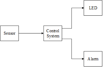
Fig. 1: Block Diagram of the Proposed Design
The block diagram consists of a sensor, a control system, an LED, and an alarm. The sensor uses infrared radiation from the human body to detect motion within its coverage area. It then sends the signal to the control system. The control system receives the sensor’s signal and sends signals to the LED and alarm for operation. The LED converts the control system’s signal into visible light, and the alarm also converts the control system’s signal into sound.
Flowchart for the Proposed Design
The flowchart for the proposed motion detection alarm system is as shown in Fig. 2. The occupant successfully activates the system by pressing the start button. The sensor stabilizes for about 10 to 60 seconds. The microcontroller has been programmed to continuously monitor the output of the PIR sensor and to activate the LEDs and buzzer. If the output of the sensor is low, the green LED blinks. However, if the output is high, the red LED blinks, and the buzzer produces a sound. Pressing the reset button restarts the entire process. If not, then both the red LED and the buzzer activate.
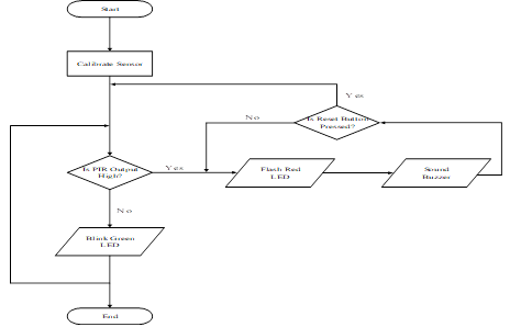
Fig. 2: Flowchart for the Proposed System
Circuit Implementation in Proteus Software
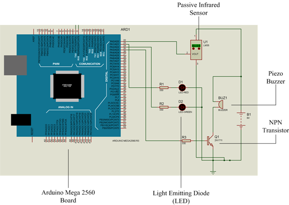
Fig. 3: Circuit Implementation in Proteus Software
A DC source (5 V), the PIR sensor module, a piezo buzzer, an ATmega 2560 microcontroller, two LEDs (red and green), three (3) resistors, each with a 100 rating, and the NPN transistor make up the circuit diagram. The DC source provides power to the PIR sensor module’s Vcc pin and the buzzer. The ATmega 2560 microcontroller connects the output pin of the PIR to its digital input pin 22. Pin 22 of the ATmega 2560 monitors the output of the PIR sensor module, triggering a high output when it detects motion.
The red and green LEDs are connected to the 23 and 24 pins, respectively, of the ATmega2560. A 100-Ω resistor is placed in series with each LED to limit the current that flows through the LEDs in order to prevent them from blowing up. During normal operation, the microcontroller activates the green LED, causing it to blink. When the microcontroller detects motion, it turns off the green LED and illuminates the red LED with blinks.
The NPN transistor, acting as a switch, also controls the piezo buzzer. A 100 resistor connects the transistor to pin 25 of the ATmega 2560. Under normal operation, the base of the transistor is open, and no current flows through to the piezo buzzer. However, upon detecting motion, the transistor’s base closes, causing the current to trigger the piezo buzzer, thereby indicating motion detection.
Prototype of System
We built the system prototype using a solderless breadboard. The Arduino Mega 2560 board obtains power from a personal computer via a USB cable.
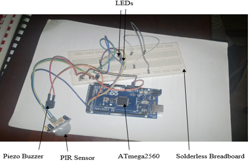
Fig. 4: Prototype of the System
As shown in Fig. 4, we connected the various components of the system to the Arduino board and the solderless breadboard.
IMPLEMENTATION AND RESULTS
The results and discussion of this project are presented in this section. The results are based on the circuit simulation outcome and the system prototype’s operation.
Simulation of the Detection System
The proposed circuit was successfully simulated using Proteus 8.2 design suite software. We carried out the simulation to determine the functionality of the proposed design. The microcontroller receives information from the PIR sensor, which determines whether to blink the red or green LED and whether to trigger the piezo buzzer. Under normal conditions, the PIR sensor’s output is low when it detects no motion. The microcontroller causes the green LED to blink while both the red LED and buzzer are off, as shown in Fig. 5. However, when motion detects abnormal conditions, the red LED blinks, the buzzer emits an alarm, and the green LED turns off (Fig. 6).
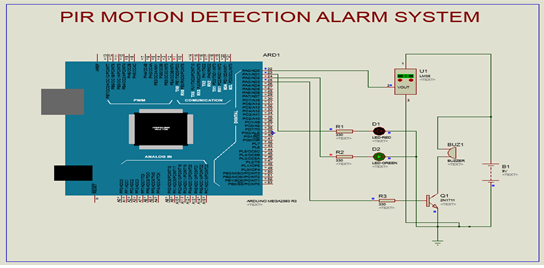
Fig. 5: Screenshot of Simulation of Designed Circuit (Green LED on)
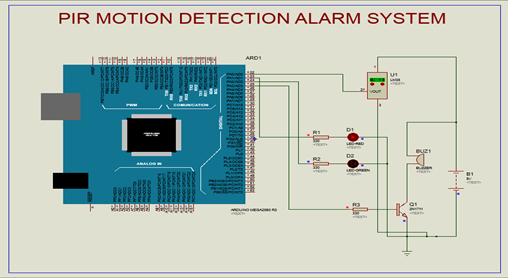
Fig. 6: Screenshot of Simulation of Designed Circuit (Red LED and Buzzer on)
Operation of System Prototype
Fig. 7 depicts the prototype of the entire system with the green LED on and the red LED and buzzer off, while Fig. 8 shows the system with the red LED and buzzer on and the green LED off.
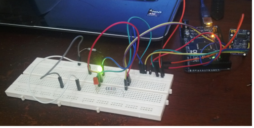
Fig. 7: System Prototype (Green LED on)
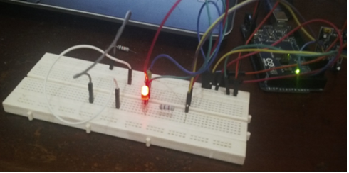
Fig. 8: System Prototype (Red LED and Buzzer on)
The design was successfully simulated using Proteus 8.2 design suite software. Motion detection was accomplished by using the PIR sensor. The use of LEDs (green and red) and a piezo buzzer ensured ease of operation. We programmed the ATmega2560 microcontroller, the main controlling device, using the Arduino IDE. The designed flowchart simplified the programming process. Simulated results indicated that the design operated accordingly.
CONCLUSION AND FUTURE WORK
This study highlights the effectiveness and practicality of using a motion sensor, specifically the passive infrared (PIR) sensor, as a cost-effective approach for detecting intruders in residential or industrial settings. Through the integration of this technology, the system not only acts as a vigilant protector against prospective burglaries but also enhances awareness of security dangers, serving as a deterrent to intruders and therefore reducing the chances of property damage and harm to tenants. This design’s proven effectiveness and cost-effectiveness highlight its promise as a practical solution for enhancing security measures.
Future work recommendations include enhancing the system’s functionality by adding an auto-dialer feature to notify authorities of breaches more quickly. Furthermore, motion detection algorithms can be embedded to distinguish between movements made by humans and animals, which will reduce false alarms and increase the system’s reliability in practical scenarios.
REFERENCES
- J. Carlsen, “Everything you need to know about home security,” Safe Wise, https://www.safewise.com/everything-you-need-to-know-about-home-security/, November 2023, (accessed May 7, 2024).
- N. Agarwal, G. S. Nayak, Microcontroller Based Home Security System with Remote Monitoring, International Conference on Electronic Design and Signal Processing, Vol. 1, No. 3 (2012), pp. 38 – 41.
- M. J. Charadva, R. V. Sejpal, N. P. Sarwade, A Study of Motion Detection Method for Smart Home System, International Journal of Innovative Research in Advance Engineering, Vol. 1, Issue 5 (2014), pp. 148 – 151.
- A. I. Omer, M. A. Alhadi, Development of a Microcontroller Based Security Lock for a Car Engine, 1st Global Virtual Conference, Vol. 1, Issue 1 (2013), pp. 502 – 505.
- Iyapo, K. O., Fasunla, O. M., Egbuwalo, S. A., Akinbobola, A. J., & Oni, O. T., Design and Implementation of Motion Detection Alarm and Security System, International Journal of Engineering and Advanced Technology Studies, 6(1) (2018), 26-38.
- Ofualagba G., Onyan A. O., Design and Implementation of a Microcontroller Based Home Security Alert System, Control Science and Engineering, vol. 1, no. 3 (2017), pp. 84-94.