
Visualizing Fluid Flows: Creating a Schlieren Imaging Apparatus
- Chinweze Arinze Everest
- Akuchi Ikenna Joshua
- Ajukwaeke Ogochukwu Sixtus
- Okafor Fred Nnabueze
- Uwazuruike Joshua Chidiebube
- 775-784
- Jun 13, 2024
- Mechanical Engineering
Visualizing Fluid Flows: Creating a Schlieren Imaging Apparatus
Chinweze Arinze Everest*, Akuchi Ikenna Joshua., Ajukwaeke Ogochukwu Sixtus, Okafor Fred Nnabueze, & Uwazuruike Joshua Chidiebube
Department of Mechanical Engineering, Nnamdi Azikiwe University, PMB 5025, Awka, Anambra, Nigeria
*Corresponding Author
DOI : https://doi.org/10.51244/IJRSI.2024.1105049
Received: 26 April 2024; Revised: 05 May 2024; Accepted: 10 May 2024; Published: 13 June 2024
ABSTRACT
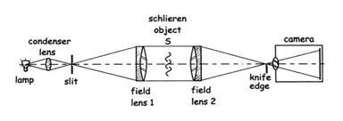
This work presents the design and fabrication of a schlieren viewing apparatus. In this work, a dual-lens schlieren arrangement was employed to visualise candle flames, gas leakage from a lighter, and gas spray from a gas nozzle. The apparatus consists of two 100mm convex lenses having a focal length of 300 mm each, a light source, a knife-edge, and a camera. The light source and knife-edge are positioned at 300 mm from the first and second lenses, respectively, and the lenses are placed at 850 mm from each other. The equipment was used to simulate candle flames, lighter gas leaking, and gas discharge from a gas nozzle. It was confirmed that the dual-lens schlieren apparatus is an effective way of visualizing different flow phenomena.
Keywords: Schlieren, lens, Knife Edge, refraction
INTRODUCTION
Schlieren photography is a technique for photographing the flow of fluids with different densities. It’s a technique for displaying density changes in transparent mediums. The Schlieren system shines a light on or behind a target object from a single collimated source. The collimated light beam is distorted by variations in a refractive index produced by density gradients in the fluid. This distortion results in a spatial change in light intensity, which can be seen using a shadowgraph system [1]. Schlieren apparatuses translate phase differences into amplitude and sometimes colour differences that we can see. Due to the limitations in the ability of the human eye to see the refraction of light as it passes through a medium of varying densities, a means of visualising the behaviour of light rays is expedient. Schlieren photography is utilised in a variety of engineering applications, including heat transfer, gas leak detection, boundary layer detachment studies, optics characterization, and liquid atomization. Bio-medicals, combustion, geophysics, industrial applications, materials processing, microscopy, optical processing, optical shop testing, and other fields benefit from it. This project aims to set up a portable schlieren imaging system, which can be used to visualize fluid flows in laboratories using a high-speed camera.
Different Types of Schlieren Set-ups
Schlieren viewing apparatus set-up has undergone several modifications since inception. But basically, there are two types of schlieren setups namely: the lens system and the mirror system. The Lens system is easier to assemble as it is often done on a single axis. The mirror system is not easily aligned on one axis as the light is reflected on a different axis. This can be an advantage in saving space. However, it implies an arrangement that is more difficult to set up. Nevertheless, the advantages are considerable: Chromatic aberration is averted for mirrors, and costs are lower than for lenses. Table 1 shows the different types of schlieren setups.
Table 1: Different Schlieren Set-Ups (Modified from source) [2]
| S/N | Schlieren Set-Up | Types of Schlierent Set Up |
| 1 |
Lens Systems |
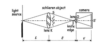
i. Toepler’s single-lens schlieren system
|
| ii. Dual-field lens schlieren system
|
||
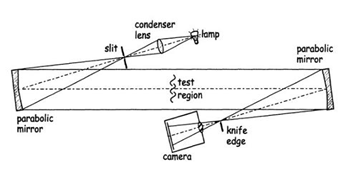
| 2 | Mirror Systems | i. Z-type schlieren arrangement
|
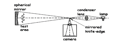
| ii. Single-mirror coincident schlieren system
|
||
| iii. Single-mirror off-axis schlieren system
|
REVIEW OF RELATED LITERATURE
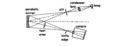
Reference [3], used a single-mirror coincident schlieren system as shown in the figure below. The system implements an LED flashlight with a structured pinhole (to create a point light source), condenser lens, half mirror (beam splitter), 12-inch diameter f/8 spherical mirror, and a series of metal and wooden blocks to use as stands. The most obvious limitations of the system currently on display are size and portability.
In a work titled “Open Schlieren.” [4], the system consists of four separate pieces: three primary members and one piece that props up a business card as the segmented background. Of the three primary members, one member holds the mirror mount and the other two members rotate the mirror at the correct distance from the phone camera.
In the Design and Construction of a Supersonic Wind Tunnel, with Diagnostics [5], a modified z-system design was introduced, the components used included the light source, 2 mirrors and mounts, knife-edge, and screen. The major problem in their work was attributed to the results they got during testing; trials with shorter distances between the mirrors did not produce optimal results.
Reference [6] carried out work to design, assemble, and calibrate a focusing schlieren system. A focusing schlieren system is a schlieren system that can focus on a narrow plane of the flow of interest. The system was built on an optical breadboard. The work is bulky and the high cost of acquiring the equipment is one of the work’s limitations.
No doubt, there are lots of schlieren viewing apparatus available in the market, but this available equipment is sophisticated, costly and not easy to maintain. For education and training purposes, there is a need for a simple, and low-cost schlieren viewing apparatus that will be easy to maintain for students to have hands-on desk training in the area of flow dynamics. This work stands out as it utilized locally available materials for the design and construction of the apparatus. This will enable the production of an apparatus that is relatively cheaper than existing ones without having any of its required standards compromised. In addition, the apparatus will be fabricated as a lab apparatus that can easily be conveyed to the lecture venue when needed and can be used as a study aid in thermodynamics and fluid mechanics.
MATERIALS AND METHODS
Materials make up the basic elements, which all manufacturing processes have to work with. In this design, we considered some factors according to their importance which include: Material availability, Machinability of the material, Strength of material, Cost of the material, Weldability of the material, rigidity of the material and durability of the material.
Table 1: Material selection table
| Component | Function | Material(s) used | Material property requirements |
| Set-up base | Supports the components of the apparatus such as retort stands. | Steel angle iron | Weldability, machinability,
Lightweight, workability, formability. |
| Softwood plywood covered with porcelain sheet | Easy to work on, less weight,
Good aesthetics. |
||
| Test stand | Serves as the base for the test object. | Steel angle iron | Weldability, machinability, less weight, workability, and formability. |
| Wooden Board | High damping capacity, less weight, and lower cost as compared to steel metal sheets. | ||
| Retort stand | Secures the convex lenses, the knife-edge and the light source in an aligned position. | Galvanized steel pipe
Mild steel sheet |
Machinability, low cost, weldability, better appearance as compared to ordinary steel, corrosion and wear resistance.
Weldability, machinability, and low cost, lightweight. |
| Convex lens | Collimates and focuses the light rays. | Glass | High transparency and precision. |
| Knife-edge | A sharp edge is needed to prevent diffraction effects at the edge. It is placed either horizontally or vertically so that the edge filters any perpendicularly diffracted light beams | Stainless steel | Corrosion resistance, smooth edges. |
METHODS
Selection of the lenses
Lenses were chosen instead of mirrors for this work because they provide better sensitivity, compactness and better magnification. The size of the lens used is a function of the space available and the focal length of the lens. The bigger the diameter of the lens, the higher the price. Limited space and portability resulted in our using 100mm diameter lenses for the project.
Camera Selection
A digital camera capable of recording high-speed events is highly recommended. With the recent development in camera technology, a camera to serve this purpose is readily available. An HD digital camera with a 1000 x 1000 pixel resolution or more, with at least 250fps Megapixels (at least 18mp for quality image), and an adjustable focal length of 490mm and above will do.
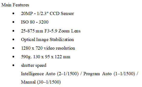
The camera selected with features (Sony Cyber-shot DSC-H300)
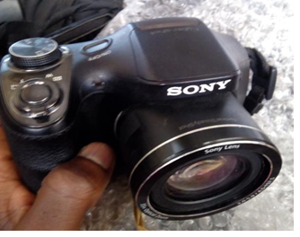
Figure 1: Sony Cyber-shot DSC-H 300
Light source
A light source of sufficiently high luminous existence (measured in lux) is required to ensure sufficient luminance in the final image. [7] Reckoned that 50 lux is needed on a ground-glass viewing screen, so the source existence should be at least 100 lux for a schlieren system at half cut-off.
Lux = lumens⁄(Square area ) (1)
- The transmittance of a lens: Transmittance (T) is defined as the ratio of the intensity of incident light to the intensity of transmitted light.
T = T = I⁄I0 (2)
- Absorbance: Absorbance (A) is expressed as:
A = log (1⁄T ) (3)
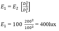
Newton’s inverse square law states that the intensity of light is inversely proportional to the square of the distance from the light source. It is given by;
 (4)
(4)
Where: E1 = intensity at a distance D1
E2 = intensity at a distance D2
D = distance from the light source
Since the total distance travelled by the light source through the setup is about 200cm and at 200cm the required intensity should be at least 100 lux
Let D2= 200cm, and E2 = 100lux;
From equation (4),
 (5)
(5)
From the set-up at a distance of 100cm, i.e. the centre of the setup, the intensity at this point is that after the first lens, which is 825lux and is greater than 400lux (calculated as the least required intensity at that point). Hence, a light source of at least 1000lux will be suitable for the maximum luminance of the image.
Designing the set-up base/frame
The set-up base design is a conventional table design with human ergonomics being considered. The apparatus in itself is considered to be operated while standing.
Height: The choice of height of a work table is determined by the kind of work carried out on the table. For heavy work, the standard height is from 0.71m to 0.89m, while for light work, a height of 0.86m to 0.94m above the floor is recommended [8]. Our table height was chosen to be 0.9 m since we are not carrying out heavy work.
The materials most suitable and locally available for the frame are 1.5″ and 1″ steel angle iron. Properties such as rigidity, strength, and the L shape gave it an advantage over the mild steel square pipe.
Length: This will depend on the length of the set-up and the clearance. Below is the block diagram representation of the setup:
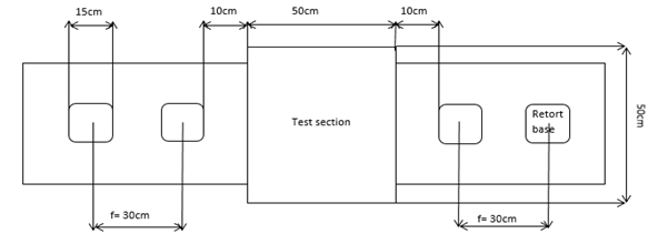
Figure 2: Selection of length for the table dimension
From figure 4, the total usable length is summed up to 160cm (7.5+30+7.5+10+50+10+7.5+30+7.5) cm. An additional clearance length of 20cm was added on both sides, to avoid the sudden falloff of components and for convenience, arriving at a total length of 200cm.
The width of the table was to be chosen considering that it is meant to allow the test section to freely move along its length without difficulty, i.e., given that the width of the test section is 50 cm, 43 cm was chosen as the width of the table, providing a clearance of about 3.5 cm on both sides.
Designing the test stand
Considerations such as test section size, expected vibration, ergonomics, and weight were taken into account during the design process. From the base design, the test-stand top is a 50cm x 50cm area.
- Height:
The test stand height is to be designed to give a clearance of 6 cm. Hence, the test stand height is
Height of the base frame (= 90cm) + clearance (= 6cm) = Height of the test stand (= 96cm). The board is softwood and the material used for the frame is a 0.5-inch steel angle. It weighs 7.58kg.
Designing the retort stand
The stands are sectioned into three parts.
The head: firmly secures the component for which it is designed. The material used is aluminium alloy.
The stalk: this is made of two galvanized steel pipes of different cross-sections and lengths. The first is fixed to the base and the other pipe to the head.
The base: For stability of the retort, we in-cooperated a 0.15 m x 0.15 m flat mild steel plate which would be screwed to the wood. The base carries the weight of the component.
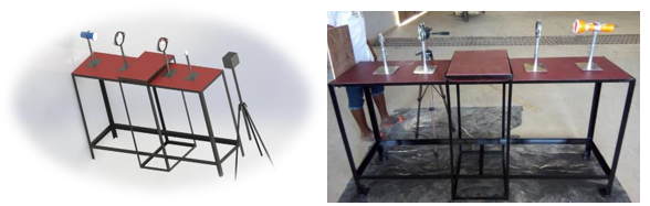
Figure 3: CAD model and fabricated apparatus
RESULTS AND DISCUSSION
Test and Applications: Experiment condition.
Shutter speed = 50, ISO = 120, Aperture = 5.6mm, Lens focus = Manual focus
Environment condition = Low light intrusion and no interference in air circulation around the test region to ensure an accurate result.
Principle Verification Testing using a candle flame
Having finished the fabrication, alignment, and installation of the schlieren system, the images of the air above a candle flame were obtained. At first, without the knife edge, from the image obtained, the difference in density in the surrounding air is not that distinguishable, as seen in figure 5. Some of the rays are refracted while some of them are deflected from the initial path. But the deflection is slightly off the initial path, thus making the difference in density not very noticeable. Introducing a knife edge cuts off some of the deflected rays, thereby increasing the contrast. As the contrast is increased, the difference in air density becomes more visible, as seen in figure 10. The small variations of the air current can be seen from the strong light and shade change in the photo. The principle experiment is also successful.
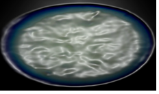
Figure 5: Schlieren image as captured without the introduction of a knife edge.
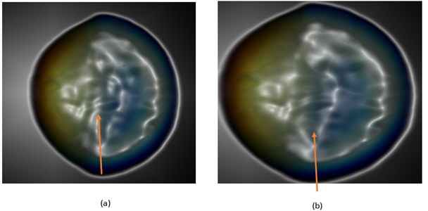
Figure 10: Schlieren image as captured when knife edge is introduced.
Gas Leak Detection
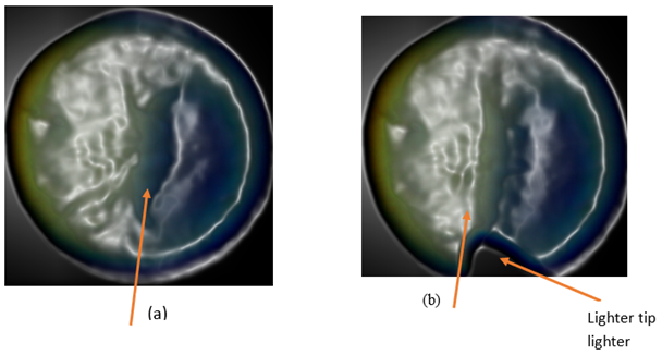
Figure 11: Gas leaking out from a lighter.
Figure 11 shows a continuous gas flow from the lighter tip, while (b) shows a fluctuation in the flow of the butane gas from the lighter tip. It is observed that the thicker streak at the centre of the image shows a concentrated butane gas while the region around it shows a diffusing butane gas, hence of less density, which is not as dark as the streak along the centre.
Gas spray from a gas nozzle:
Figure 12 below shows images of gas spray from a nozzle. In images a and b, the nozzle tip is placed within the test region, so the gas can be seen emerging from the nozzle tip. It is observed that the density of the flow decreases as the gas diffuses. While in images b and c, the nozzle tip is placed outside the test region, and it is observed that the density of the seen gas appears more diffuse and less dense.
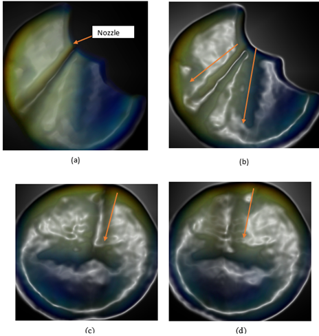
Figure 12: Gas spray from a gas nozzle
LIMITATIONS AND CONCLUSION
Limitations
During the design and fabrication process of our schlieren imaging apparatus, several limitations and challenges emerged, hindering smooth progress. One notable challenge was the selection of suitable materials for construction. Limited availability of materials and constraints on cost-effectiveness posed significant hurdles. To address this, future researchers could conduct more extensive surveys of material options, considering not only their properties but also their local availability and cost implications. Additionally, difficulties in precise alignment during assembly presented challenges, leading to potential inaccuracies in the apparatus. Implementing advanced alignment tools and techniques, such as laser alignment systems or precision machining, could mitigate these issues and ensure more accurate assembly in future projects.
Another challenge encountered was the complexity of the setup process, particularly in achieving optimal positioning of components such as lenses and light sources. This complexity could potentially deter researchers from pursuing similar projects. To overcome this obstacle, comprehensive documentation of assembly procedures, along with detailed instructional materials, could prove invaluable. Providing step-by-step guidance and troubleshooting tips would assist future researchers in navigating the setup process more efficiently.
Furthermore, limitations in the capabilities of the imaging system, such as chromatic aberrations and suboptimal image quality, presented additional challenges. To address these limitations, incorporating advanced features such as high-focusing lenses, graduated filters, or laser light sources could significantly enhance image quality and overall performance. By investing in these upgrades, future researchers can overcome these obstacles and unlock the full potential of their schlieren imaging apparatus for fluid dynamics research.
Conclusion
In conclusion, our study on the design and fabrication of a schlieren imaging apparatus, we’ve achieved a significant milestone in the realm of fluid dynamics research. Through the implementation of a dual-lens schlieren arrangement, we successfully visualized diverse flow phenomena, ranging from the flickering dance of candle flames to the subtle release of gas from a nozzle. This underscores the efficacy of our apparatus in capturing intricate flow dynamics. By meticulously considering factors such as material availability, machinability, and cost-effectiveness, we’ve developed a solution tailored for educational contexts, where accessibility and affordability are paramount. Though we encountered challenges along the way, including material selection dilemmas and alignment complexities, our perseverance paid off, resulting in a valuable tool for hands-on training in fluid mechanics and heat transfer.
Looking towards future research directions, we propose integrating advanced features into the schlieren imaging system to enhance its capabilities. Incorporating high-focusing lenses could rectify chromatic aberrations and improve image clarity, while graduated filters offer a more effective alternative to razor-blade cut-offs. Furthermore, the adoption of laser light sources opens doors to capturing elusive phenomena such as shock waves and sound waves, expanding the applicability of the apparatus. Embracing these advancements not only enhances image quality but also unlocks new avenues for exploration in fluid dynamics research.
ACKNOWLEDGEMENTS
This research did not receive any specific grant from funding agencies in the public, commercial, or not-for-profit sectors.
REFERENCES
- Cyril Mauger, Loïc Méès, Marc Michard, Alexandre Azouzi, Stéphane Valette. Shadowgraph, Schlieren and interferometry in a 2D cavitating channel flow. Experiments in Fluids, Springer Verlag (Germany), 2012, 53 (6), pp.1895-1913.
- Settles G.S. (2001). Schlieren and Shadowgraph Techniques. Visualizing Phenomena in Transparent Media. (1st Edition). Springer-Verlag, Berlin, Germany
- Mazumdar .A. (2013). Principles and Techniques of Schlieren Imaging Systems. (BSc. Project) Department of Computer Science, Columbia University.
- Miller A. Victor and Keith T. Loebner, (2016). Smartphone Schlieren. Semantic Scholar (1-7)
- William B, Katheiine F., Geordie F, Nathan C, Gallagher H, Markus I, Joshua L, Neel P, Dong-Uk S, Grant W, and Earl Z (2013). Design and Construction of a Supersonic Wind Tunnel with Diagnostics. (BSc Project). Worcester Polytechnic Institute. Pg 56-64
- Daniel Floryan, Jerrod Hofferth, and William Saric, (2012). Design, Assembly, and Calibration of a Focusing Schlieren System. Technical Report. 1-11
- John Stuart Goulding (2006). A STUDY OF LARGE-SCALE FOCUSING SCHLIEREN SYSTEMS. (MSc). Faculty of Engineering and the Built Environment, University of the Witwatersrand, Johannesburg
- Maguire Richard (2013). Workbench Designs. The English Woodworker. As Retrieved From Http://Www.Theenglishwoodworker.Com/Workbe nch-Height/