
Studying the Performance of Different Transforms in Face Image Authentication Technology
- Rasha Thabit
- Asmaa Hatem Jawad
- Doaa Subhi
- Khamis A. Zidan
- 631-646
- Sep 6, 2024
- Education
Studying the Performance of Different Transforms in Face Image Authentication Technology
Rasha Thabit1, Asmaa Hatem Jawad1, Doaa Subhi2, Khamis A. Zidan3
1Department of Computer Engineering, College of Engineering, Al-Iraqia University, Baghdad, Iraq
2Network Engineering and Cyber Security Department, College of Engineering, Al-Iraqia University, Baghdad, Iraq
3Vice Rector of Al-Iraqia University for Scientific Affairs, Al-Iraqia University, Baghdad, Iraq
DOI: https://doi.org/10.51244/IJRSI.2024.1108051
Received: 09 August 2024; Accepted: 21 August 2024; Published: 06 September 2024
ABSTRACT
The rapid spread of face image manipulation applications and the malevolent uses of the manipulated face images have been considered as an alarm for information security specialists. Inspired by the urgent need of face image manipulation reveal, various researches have been introduced to serve this purpose. The recent direction of developing face image authentication (FIA) technology has been directed towards combinations of various image processing techniques such as face area detection, image watermarking, tamper detection, tamper localization, and image recovery. In this paper, FIA scheme has been implemented based on various transforms such as Discrete Cosine Transform (DCT), Integer Wavelet Transform (IWT), and Slantlet Transform (SLT). The aims of this paper is to study the performance of these transforms in FIA technology and choose the one with the best results in addition to improving the embedding capacity. The first part of experimental work has been dedicated for testing the performance of the transforms which proved that the SLT obtained the best visual quality results. The second part of the experimental work have been dedicated for testing the SLT-based FIA scheme. The results proved that the scheme can successfully detect manipulated blocks in the face region and recover the original face region with good visual quality. The proposed FIA scheme proved its effectiveness compared to the state-of-the-art watermarking-based schemes; therefore, it is recommended for practical applications.
Keywords— Face image authentication, Face image manipulation detection, Deepfakes reveal, Deepfakes detection, Slantlet-based watermarking
INTRODUCTION
An Technology is always developing, making it easier to share digital photographs for a variety of uses. On the other hand, many people now realize that storing their private images and important information in the cloud makes it handy to access them at any time [1]. However, security and data integrity continue to be the key worries of users. A number of techniques and security frameworks, including steganography [2], cryptography [3], [4], and watermarking [5]–[7], have been developed to address these issues and guarantee the security of shared data and digital images. With these advancements, the methods and instruments for digitally modifying facial photographs have become more widely available. The techniques for manipulating the face image can be broadly divided into two categories: intentional attacks, which are done with malicious intent, and unintentional attacks, which are done for benign objectives like enhancing appearance or include enjoyable features [8]–[11]. Both forms of alteration result in modifications to the image’s original face features, although having distinct reasons for doing so.
Along with voice, fingerprint, and iris recognition, biometric security technologies also include the Face Recognition System (FRS) [12]–[14]. Because it can decide whether a picture is accepted or denied, the quality of photographs utilized in FRS is quite important. A fake image that gets approved by the system poses a serious threat to privacy since it can undermine the whole security system. Intentional facial image manipulations (FIM) can result in serious problems such as financial fraud, political unrest brought on by false information, identity theft, and more [15]–[17].
Researchers have been working on creating detection methods to distinguish between real and fake face images due to the surge in dangerous FIM applications. Since the Deepfakes are deep-learning (DL) based, various Face Image Manipulation Detection (FIMD) techniques have been presented based on DL [18]–[21], however, these techniques have some limitations as mentioned in [17], [22]. The main limitations are: the need for knowing the conducted manipulation method in order to choose the right detection method, the need for huge and high-quality image datasets for training, the long time required for training the networks, and lack of generalization. To overcome the limitations, the watermarking-based FIMD schemes have been recently presented [23]–[27].
In [23], [24], the FIMD scheme has been implemented using face window detection algorithm and image watermarking techniques. The algorithm at the sender side starts by the binary mask image generation in which the face window is detected using Multi-Task Cascaded Neural Network (MTCNN) followed by the process of pixels identification and selection from which the mask image can be calculated. Then, the generated mask image and the original face image are divided into blocks each of size (16×16) pixels. Thereafter, the mean value of each block from the mask image is calculated to classify the blocks of the face image into two types that are either belong to the face window or belong to the area outside the face window. The localization data have been generated from the rounded mean value of each block that belongs to the face window. The localization data has been converted to binary and embedded in the blocks that are outside the face window using content-based embedding algorithm based on the watermarking techniques in [28]–[30]. At the receiver side, the procedure of detecting the face window and generating the binary mask image is conducted followed by dividing the mask image and the watermarked face region into blocks each of size (16×16) pixels. The blocks of the watermarked face image are also classified into two groups and the localization data are extracted from the blocks that are outside the face window. The mean values of the blocks belong to the face window are calculated and compared with the extracted values. If the calculated mean values and the extracted mean values are identical, the face image is considered authentic, otherwise, the tamper localization process is conducted by drawing a border on the block that has been modified. The scheme proved its efficiency compared to DL-based techniques; however, it cannot recover the original face region when manipulations present. To provide the ability of recovering the original face region after detecting manipulation, the research in [25] suggested the use of different face region recovery algorithms that are average (2×2) pixels, Integer Wavelet Transform (IWT), and Bicubic Interpolation (BI). The BI algorithm proved its efficiency compared to the other recovery algorithms thus it has been included to improve the authentication algorithms that have been adopted from [24] to introduce a new Face Image Authentication (FIA) scheme [26]. The scheme can localize the tampered regions and recover the original face region with good visual quality; however, the increase of tamper detection and recovery data require more embedding capacity to embed the generated data. When the face image has limited capacity, the scheme cannot be used.
To improve the embedding capacity and to obtain high visual quality, this paper suggests a new embedding method with different image transforms. As conducted in [23]–[27] schemes, the proposed scheme also starts by detecting the face window and generating the binary mask image. Then the mask image and the face image are divided into blocks each of size (16×16) pixels. The localization data are generated by calculating the mean values. The recovery data are generated using BI algorithm. Unlike the schemes in [23]–[27] which uses horizontal and vertical subbands of the transformed block to carry the binary sequence, this paper suggests the embedding of the resultant binary sequence generated from the localization and recovery data in the transformed blocks by modifying the neighboring pairs of coefficients in the horizontal, vertical, and diagonal subbands. The main contributions of this paper are the improvement in the embedding capacity and the investigation of different transforms to choose the best one for FIA.
The remaining portion of the paper discusses the suggested scheme’s methodology, the tests run to gauge its effectiveness, the findings, and the related discussions.
Proposed Scheme
The proposed FIA scheme consists of two main algorithms that are applied at the sender side and the receiver side. The general block diagrams of the proposed algorithms are shown in Fig. 1 and Fig. 2. The details of the proposed algorithms are illustrated in the following subsections.
Proposed scheme at the sender side
The proposed FIA scheme at the sender side starts by reading the input face image and generating the binary mask image. The three channels of the color face image are separated to apply the embedding procedure on each channel. The resultant watermarked channels are rearranged to construct the watermarked face image. The procedure at the sender side can be summarized as shown in Fig. 1 and the steps of the algorithm are as follows:
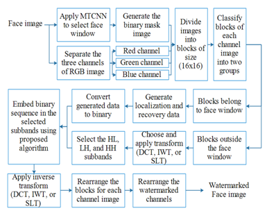
Fig. 1 Proposed FIA scheme at the sender side.
Step 1: Read input face image \( I_f \) of size \( M \times N \times 3 \).
Step 2: Apply the MTCNN-based algorithm to detect the face window and adjust its outputs as explained in [24]. The outputs of this step are the selected face region and the generated mask image \( I_M \).
Step 3: Divide \( I_f \) channels and \( I_M \) into blocks, then classify the image blocks into two groups. The procedure is as follows:
- Read one channel from \( I_f \) (ch).
- Divide both ch and \( I_M \) into blocks, each of size \( 16 \times 16 \) pixels.
- Classify the ch blocks into two groups called face blocks and non-face blocks and save the block into two arrays called Face block (FB) and Non-Face Block (NFB), respectively, based on the equation:
\[
\text{Average of } I_M \text{ block} = 0 \Rightarrow \text{ch block} \in \text{NFB}
\]
\[
\text{Average of } I_M \text{ block} \neq 0 \Rightarrow \text{ch block} \in \text{FB}
\]
Step 4: Generate the first part of the secret binary sequence, which will be adopted for localizing the tampered blocks at the receiver side. The procedure of this process is as follows:
- Calculate the mean value of each block in the FB array.
- Convert each mean value to a binary sequence of length 8 bits.
- Concatenate the resultant binary sequences into one binary sequence called “bin-seq1”.
Step 5: Generate the second part of the secret binary sequence, which will be adopted for recovering the face region at the receiver side. The procedure of this process is as follows:
- Apply bicubic interpolation on the detected face region.
- Convert the resultant pixels into binary sequences, each of length 8 bits.
- Concatenate the binary sequences into one binary sequence called “bin-seq2”.
Step 6: Concatenate the binary sequences “bin-seq1” and “bin-seq2” to generate a single sequence called “bin-seq”.
Step 7: To prevent errors and enhance the strength of the binary sequence “bin-seq,” Bose-Chaudhuri-Hocquenghem (BCH) coding \((15,11)\) is applied. This coding scheme generates 15 bits in the coded sequence for every 11 bits. To ensure the length of the “bin-seq” is divisible by 11, “extend 1” rules are applied as follows:
- If \(\text{Reminder}\left(\frac{\text{length}(\text{bin-seq})}{11}\right) \neq 0\), then:
- \(Z_1 = 11 – \text{Reminder}\left(\frac{\text{length}(\text{bin-seq})}{11}\right)\)
- Where \(Z_1\) refers to the number of zeros required for “extend 1”.
- Then “bin-seq” is extended by \(Z_1\) zeros followed by applying BCH coding.
Step 8: The binary sequence is divided into windows, each of length 96 bits, to be embedded in NFB. Therefore, the length of the binary sequence must be divisible by 96. Accordingly, “extend 2” rules are applied as follows:
- If \(\text{Reminder}\left(\frac{\text{length}(\text{coded seq.})}{96}\right) \neq 0\), then:
- \(Z_2 = 96 – \text{Reminder}\left(\frac{\text{length}(\text{coded seq.})}{96}\right)\)
- Where \(Z_2\) refers to the number of zeros required for “extend 2”.
- The resultant sequence after coding is extended by \(Z_2\) zeros. The final generated sequence is saved as “Bseq”.
Step 9: The resultant “Bseq” is divided into subsequences, each of length 96 bits, and each subsequence is embedded in a block from NFB after applying transform and selecting the carrier subbands (HL, LH, and HH). The procedure is as follows:
- Read a block from NFB and apply transformation (DCT, IWT, or SLT). The resultant subbands are called approximation or Low-Low (LL), horizontal or High-Low (HL), vertical or Low-High (LH), and diagonal or High-High (HH).
- The HL, LH, and HH subbands are selected to carry the binary sequence.
- Read the window of binary sequence (W) and divide it into 3 sub-windows, each of length 32 bits, named \(W_1\), \(W_2\), and \(W_3\).
- Where \(W_1 = W(1:32)\), \(W_2 = W(33:64)\), and \(W_3 = W(65:96)\).
- Apply the following steps to embed \(W_1\), \(W_2\), and \(W_3\) in HL, LH, and HH subbands, respectively, to obtain NewHL, NewLH, and NewHH.
Step 10: Construct the watermarked face image from the three watermarked channels.
Proposed scheme at the receiver side
The proposed FIA scheme at the receiver side starts by reading the watermarked face image and generating the binary mask image. The three channels of the color face image are separated to apply the extraction procedure on each channel. The extracted localization data and the calculated localization data are compared to decide if the received watermarked image is authentic or not authentic. The procedure at the receiver side can be summarized as shown in Fig. 2 and the steps of the algorithm are as follows:
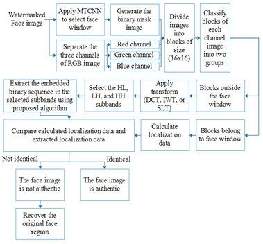
Fig. 2 Proposed FIA scheme at the receiver side.
Step 1: Read watermarked face image \(WIf\) of size \(M \times N \times 3\).
Step 2: Apply the MTCNN-based algorithm to detect the face window and adjust its outputs. The outputs of this step are the selected face region and the generated mask image \(IM\).
Step 3: Divide \(WIf\) channels and \(IM\) into blocks, then classify the image blocks into two groups. The procedure is as follows:
- Read one channel from \(WIf\) (Wch).
- Divide both Wch and \(IM\) into blocks, each of size \(16 \times 16\) pixels.
- Classify the Wch blocks into two groups called face blocks and non-face blocks and save the block into two arrays called FB and NFB.
Step 4: Calculate the mean values for FB and save them for later comparison steps.
Step 5: Extract the embedded subsequence from NFB using the proposed algorithm as follows:
- Read NFB block and apply transformation.
- Extract the embedded binary window \(W_1\), \(W_2\), and \(W_3\) from carrier subbands.
- Apply the following steps to extract Bseq from HL, LH, and HH subbands, respectively.
Let the subband (Sb) and the extracted binary sequence (W), which is of length 32 bits.
\(W_{counter} = 1\);
For \(Row_{Sb} = 1\) to 8
For \(Col_{Sb} = 1\) to 2 to 8
If \(Sb(Row_{Sb}, Col_{Sb}) \geq Sb(Row_{Sb}, Col_{Sb} + 1)\)
Then \(b = 1\) (where \(b\) refers to extracted binary bit)
If \(Sb(Row_{Sb}, Col_{Sb}) < Sb(Row_{Sb}, Col_{Sb} + 1)\)
Then \(b = 0\)
\(W(W_{counter}) = b\)
\(W_{counter} = W_{counter} + 1\)
End For loop
End For loop
Step 6: Repeat step 5 to extract the embedded .
Step 7: Retrieve the original localization data and recovery data from the extracted as follows:
- Read .
- Remove the zeros that have been added in “extend 2”.
- Apply inverse BCH coding (15,11,1) then remove the zeros that have been added in “extend 1” to obtain “bin-seq”.
- Divide the bin-seq into two parts: localization bits “bin_seq1” and
- recovery bits “bin_seq2”.
- Rearrange “bin_seq1” into subsequences each of length 8 bits and convert the resultant subsequences to decimal to obtain original mean values.
- Rearrange “bin_seq2” into subsequences each of length 8 bits and convert the resultant subsequences to decimal to obtain the recovered pixels.
Step 8: Compare the calculated localization data with the extracted localization data. If the values for each block are identical that means WIf is authentic, else, WIf is not authentic.
Step 9: When the WIf is not authentic, recover the face region form the extracted recovery data.
The proposed embedding and extraction algorithms for the carrier blocks are summarized in Fig. 3.
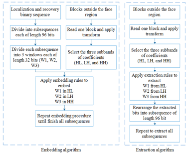
Fig. 3 The proposed embedding and extraction algorithms for the carrier blocks.
Experimental Results
The proposed FIA algorithms have been implemented using the MATLAB platform in a computer with Core i7 processor, 8 GB of RAM, and 2.30 GHz (4 CPUs). Experiments were conducted on colored face images of various sizes which were collected from different websites and a dataset such as [31], [32]. Samples of the test images are shown in Fig. 4.
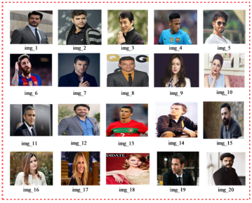
Fig. 4 Sample test images.
Visual quality test
To test the effect of the suggested transforms (i.e., DCT, IWT, and SLT) on the visual quality of the watermarked images, the Peak-Signal-to-Noise Ratio (PSNR), Mean Square Error (MSE), and Structural Similarity Index (SSIM) have been calculated. Table I to Table IV present the results of testing DCT, different families of IWT, and SLT. Table V shows the comparison results for the tested transforms which proved that the SLT gives the highest visual quality results.
TABLE I
Visual quality test results for DCT-based watermarking
| Image
No. |
Image size | Size of the
face area |
PSNR | MSE | SSIM |
| 1 | 236×213×3 | 80× 64×3 | 38.2040 | 9.83284 | 0.976423 |
| 2 | 227×222×3 | 80×64 ×3 | 33.8600 | 26.735 | 0.964043 |
| 3 | 192×262×3 | 80×64 ×3 | 37.8000 | 10.7916 | 0.985701 |
| 4 | 194×259×3 | 64× 64×3 | 42.4452 | 3.70302 | 0.991116 |
| 5 | 194×259×3 | 80× 64×3 | 41.4260 | 4.68253 | 0.986355 |
| 6 | 183×275×3 | 64× 64×3 | 37.3845 | 11.875 | 0.984187 |
| 7 | 225×225×3 | 80× 64×3 | 41.6867 | 4.40969 | 0.992648 |
| 8 | 266×190×3 | 80×64 ×3 | 37.5997 | 11.3009 | 0.964869 |
| 9 | 184×274×3 | 80×64 ×3 | 38.6409 | 8.89185 | 0.983894 |
| 10 | 183×275×3 | 80×64 ×3 | 40.8775 | 5.31283 | 0.988156 |
| 11 | 182×276×3 | 80× 64×3 | 40.2157 | 6.18741 | 0.981619 |
| 12 | 259×194×3 | 64×64 ×3 | 40.3302 | 6.02649 | 0.990726 |
| 13 | 237×213×3 | 64× 64×3 | 42.7628 | 3.44194 | 0.993477 |
| 14 | 251×201×3 | 64×64×3 | 37.4229 | 11.7703 | 0.981029 |
| 15 | 179×281×3 | 64×64×3 | 43.1592 | 3.14166 | 0.993130 |
| 16 | 192×262×3 | 64×64×3 | 39.9985 | 6.50467 | 0.993024 |
| 17 | 168×300×3 | 80×64×3 | 38.8762 | 8.4229 | 0.992825 |
| 18 | 265×190×3 | 80×64×3 | 32.1974 | 39.2046 | 0.988463 |
| 19 | 192×262×3 | 80×64×3 | 41.5955 | 4.50326 | 0.982338 |
| 20 | 240×210×3 | 80×64×3 | 39.1779 | 7.85754 | 0.974905 |
TABLE II
Visual quality test results for IWT-based watermarking
| Image
No. |
Image size | PSNR
IWT (cdf 1.1) |
PSNR
IWT (cdf 1.3) |
PSNR
IWT (cdf 1.5) |
PSNR
IWT (cdf 3.5) |
| 1 | 236×213×3 | 35.4222 | 35.2054 | 35.0695 | 32.4701 |
| 2 | 227×222×3 | 32.7172 | 32.4821 | 32.3215 | 31.3235 |
| 3 | 192×262×3 | 34.3412 | 34.1157 | 33.9674 | 31.4327 |
| 4 | 194×259×3 | 40.5949 | 40.2879 | 40.1545 | 35.2584 |
| 5 | 194×259×3 | 38.8564 | 38.5535 | 38.3959 | 32.907 |
| 6 | 183×275×3 | 34.9932 | 34.7447 | 34.5943 | 34.4705 |
| 7 | 225×225×3 | 38.497 | 38.224 | 38.0871 | 36.0831 |
| 8 | 266×190×3 | 34.9933 | 34.7324 | 34.5823 | 31.2048 |
| 9 | 184×274×3 | 35.9404 | 35.6992 | 35.5559 | 34.6916 |
| 10 | 183×275×3 | 38.1318 | 37.8856 | 37.7553 | 29.757 |
| 11 | 182×276×3 | 37.1989 | 36.9647 | 36.827 | 33.0794 |
| 12 | 259×194×3 | 36.6947 | 36.4063 | 36.247 | 32.2251 |
| 13 | 237×213×3 | 40.7716 | 40.4568 | 40.3325 | 35.0472 |
| 14 | 251×201×3 | 34.6403 | 34.4087 | 34.262 | 30.5991 |
| 15 | 179×281×3 | 39.8196 | 39.5508 | 39.4227 | 35.7499 |
| 16 | 192×262×3 | 37.6456 | 37.384 | 37.2437 | 34.3362 |
| 17 | 168×300×3 | 36.5054 | 36.2476 | 36.0956 | 34.3637 |
| 18 | 265×190×3 | 30.7393 | 30.5785 | 30.4537 | 29.4349 |
| 19 | 192×262×3 | 37.8713 | 37.6391 | 37.5116 | 36.5795 |
| 20 | 240×210×3 | 36.1478 | 35.9223 | 35.7915 | 30.7018 |
TABLE III
Visual quality test results for IWT (cdf 1.1)-based watermarking
| Image
No. |
Image size | Size of the
face area |
PSNR | MSE | SSIM |
| 1 | 236×213×3 | 80× 64×3 | 35.4222 | 18.6577 | 0.966292 |
| 2 | 227×222×3 | 80×64 ×3 | 32.7172 | 34.7827 | 0.963727 |
| 3 | 192×262×3 | 80×64 ×3 | 34.3412 | 23.9312 | 0.979668 |
| 4 | 194×259×3 | 64× 64×3 | 40.5949 | 5.67004 | 0.983936 |
| 5 | 194×259×3 | 80× 64×3 | 38.8564 | 8.46137 | 0.977434 |
| 6 | 183×275×3 | 64× 64×3 | 34.9932 | 20.595 | 0.97554 |
| 7 | 225×225×3 | 80× 64×3 | 38.497 | 9.1913 | 0.987511 |
| 8 | 266×190×3 | 80×64 ×3 | 34.9933 | 20.5947 | 0.957952 |
| 9 | 184×274×3 | 80×64 ×3 | 35.9404 | 16.5593 | 0.972092 |
| 10 | 183×275×3 | 80×64 ×3 | 38.1318 | 9.99762 | 0.981345 |
| 11 | 182×276×3 | 80× 64×3 | 37.1989 | 12.3933 | 0.965215 |
| 12 | 259×194×3 | 64×64 ×3 | 36.6947 | 13.9191 | 0.983334 |
| 13 | 237×213×3 | 64× 64×3 | 40.7716 | 5.44399 | 0.988314 |
| 14 | 251×201×3 | 64×64×3 | 34.6403 | 22.3384 | 0.972524 |
| 15 | 179×281×3 | 64×64×3 | 39.8196 | 6.77835 | 0.986644 |
| 16 | 192×262×3 | 64×64×3 | 37.6456 | 11.1819 | 0.990977 |
| 17 | 168×300×3 | 80×64×3 | 36.5054 | 14.539 | 0.988921 |
| 18 | 265×190×3 | 80×64×3 | 30.7393 | 54.8465 | 0.986738 |
| 19 | 192×262×3 | 80×64×3 | 37.8713 | 10.6158 | 0.966278 |
| 20 | 240×210×3 | 80×64×3 | 36.1478 | 15.7871 | 0.960244 |
TABLE IV
Visual quality test results for SLT-based watermarking
| Image
No. |
Image size | Size of the
face area |
PSNR | MSE | SSIM |
| 1 | 236×213×3 | 80× 64×3 | 38.6816 | 8.80893 | 0.98327 |
| 2 | 227×222×3 | 80×64 ×3 | 34.6622 | 22.2261 | 0.976027 |
| 3 | 192×262×3 | 80×64 ×3 | 38.4104 | 9.37643 | 0.990033 |
| 4 | 194×259×3 | 64× 64×3 | 42.8363 | 3.38412 | 0.992216 |
| 5 | 194×259×3 | 80× 64×3 | 42.1154 | 3.99518 | 0.988627 |
| 6 | 183×275×3 | 64× 64×3 | 37.5488 | 11.4341 | 0.986832 |
| 7 | 225×225×3 | 80× 64×3 | 41.7546 | 4.34129 | 0.993409 |
| 8 | 266×190×3 | 80×64 ×3 | 37.4241 | 11.7671 | 0.974666 |
| 9 | 184×274×3 | 80×64 ×3 | 39.3577 | 7.539 | 0.986493 |
| 10 | 183×275×3 | 80×64 ×3 | 40.9707 | 5.20013 | 0.990378 |
| 11 | 182×276×3 | 80× 64×3 | 40.6569 | 5.58978 | 0.983809 |
| 12 | 259×194×3 | 64×64 ×3 | 40.5065 | 5.78676 | 0.992382 |
| 13 | 237×213×3 | 64× 64×3 | 42.9169 | 3.32192 | 0.994238 |
| 14 | 251×201×3 | 64×64×3 | 38.1424 | 9.97334 | 0.986493 |
| 15 | 179×281×3 | 64×64×3 | 43.5922 | 2.84356 | 0.993969 |
| 16 | 192×262×3 | 64×64×3 | 40.351 | 5.99761 | 0.995697 |
| 17 | 168×300×3 | 80×64×3 | 39.0416 | 8.10811 | 0.994069 |
| 18 | 265×190×3 | 80×64×3 | 32.824 | 33.9376 | 0.990969 |
| 19 | 192×262×3 | 80×64×3 | 41.3036 | 4.81634 | 0.983831 |
| 20 | 240×210×3 | 80×64×3 | 39.4568 | 7.36888 | 0.980898 |
TABLE V
Comparison of PSNR for the three tested transforms
| Image
No. |
Image size | Size of the
face area |
SLT | IWT
cdf 1.1 |
DCT |
| 1 | 236×213×3 | 80× 64×3 | 38.6816 | 35.4222 | 38.204 |
| 2 | 227×222×3 | 80×64 ×3 | 34.6622 | 32.7172 | 33.86 |
| 3 | 192×262×3 | 80×64 ×3 | 38.4104 | 34.3412 | 37.8 |
| 4 | 194×259×3 | 64× 64×3 | 42.8363 | 40.5949 | 42.4452 |
| 5 | 194×259×3 | 80× 64×3 | 42.1154 | 38.8564 | 41.426 |
| 6 | 183×275×3 | 64× 64×3 | 37.5488 | 34.9932 | 37.3845 |
| 7 | 225×225×3 | 80× 64×3 | 41.7546 | 38.497 | 41.6867 |
| 8 | 266×190×3 | 80×64 ×3 | 37.4241 | 34.9933 | 37.5997 |
| 9 | 184×274×3 | 80×64 ×3 | 39.3577 | 35.9404 | 38.6409 |
| 10 | 183×275×3 | 80×64 ×3 | 40.9707 | 38.1318 | 40.8775 |
| 11 | 182×276×3 | 80× 64×3 | 40.6569 | 37.1989 | 40.2157 |
| 12 | 259×194×3 | 64×64 ×3 | 40.5065 | 36.6947 | 40.3302 |
| 13 | 237×213×3 | 64× 64×3 | 42.9169 | 40.7716 | 42.7628 |
| 14 | 251×201×3 | 64×64×3 | 38.1424 | 34.6403 | 37.4229 |
| 15 | 179×281×3 | 64×64×3 | 43.5922 | 39.8196 | 43.1592 |
| 16 | 192×262×3 | 64×64×3 | 40.351 | 37.6456 | 39.9985 |
| 17 | 168×300×3 | 80×64×3 | 39.0416 | 36.5054 | 38.8762 |
| 18 | 265×190×3 | 80×64×3 | 32.824 | 30.7393 | 32.1974 |
| 19 | 192×262×3 | 80×64×3 | 41.3036 | 37.8713 | 41.5955 |
| 20 | 240×210×3 | 80×64×3 | 39.4568 | 36.1478 | 39.1779 |
Capacity and payload test
The payload and capacity of each image vary depending on the size and face area of the input image. Table VI displays samples of the experiment’s results, demonstrating that a larger number of blocks in NFB than in FB will result in a higher capacity. This is because each NFB block has the potential to hold 96 bits; the capacity of an NFB block is calculated by multiplying its total number of blocks by 96 bits. The number of bits generated by FB following the application of the “extend 2” process is known as the payload. Table VI displays the obtained results. The payload increases as the number of FB blocks increases, as indicated by the results.
TABLE VI
Results of capacity and payload tests for sample test images
| Image
No. |
Image size | No. of NFB
Blocks |
Capacity
(bits) |
Single
channel payload (bits) |
Total
payload (bits) |
| 1 | 236×213×3 | 152×3 | 43776 | 14304 | 42912 |
| 2 | 227×222×3 | 152×3 | 43776 | 14304 | 42912 |
| 3 | 192×262×3 | 162×3 | 46656 | 14304 | 42912 |
| 4 | 194×259×3 | 167×3 | 48096 | 11520 | 34560 |
| 5 | 194×259×3 | 162×3 | 46656 | 14304 | 42912 |
| 6 | 183×275×3 | 162×3 | 46656 | 11520 | 34560 |
| 7 | 225×225×3 | 166×3 | 47808 | 14304 | 42912 |
| 8 | 266×190×3 | 151×3 | 43488 | 14304 | 42912 |
| 9 | 184×274×3 | 157×3 | 45216 | 14304 | 42912 |
| 10 | 183×275×3 | 157×3 | 45216 | 14304 | 42912 |
| 11 | 182×276×3 | 157×3 | 45216 | 14304 | 42912 |
| 12 | 259×194×3 | 167×3 | 48096 | 11520 | 34560 |
| 13 | 237×213×3 | 162×3 | 46656 | 11424 | 34272 |
| 14 | 251×201×3 | 155×3 | 44640 | 11520 | 34560 |
| 15 | 179×281×3 | 162×3 | 46656 | 11520 | 34560 |
| 16 | 192×262×3 | 172×3 | 49536 | 11424 | 34272 |
| 17 | 168×300×3 | 150×3 | 43200 | 14304 | 42912 |
| 18 | 265×190×3 | 152×3 | 43776 | 14304 | 42912 |
| 19 | 192×262×3 | 162×3 | 46656 | 14304 | 42912 |
| 20 | 240×210×3 | 165×3 | 47520 | 14304 | 42912 |
Authentication test
The proposed FIA scheme has been tested for different manipulations to ensure its efficiency and the results proved its ability to detect various attacks start from small modification to entire face swap. The results of manipulations localization and original face region recovery are shown in Fig. 5 to Fig. 7.
Comparison with previous schemes
The proposed FIA scheme improved the capacity by embedding 96 bits in each NFB while the previous schemes can embed only 64 bits in each block. Table VII illustrates the comparison results for the sample test images which proved that the proposed scheme has higher embedding capacity results and thus more face images can be protected using the proposed FIA scheme.
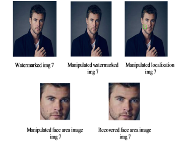
Fig. 5 Authentication results for test image ‘img 7’.
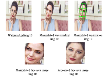
Fig. 6 Authentication results for test image ‘img 10’..
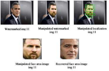
Fig. 7 Authentication results for test image ‘img 11’.
TABLE VII
Results of capacity and payload tests for sample test images
| Image
No. |
No. of NFB
Blocks |
Capacity
(bits) Proposed |
Capacity
(bits) [24] |
Capacity
(bits) [26] |
| 1 | 152×3 | 43776 | 29184 | 29184 |
| 2 | 152×3 | 43776 | 29184 | 29184 |
| 3 | 162×3 | 46656 | 31104 | 31104 |
| 4 | 167×3 | 48096 | 32064 | 32064 |
| 5 | 162×3 | 46656 | 31104 | 31104 |
| 6 | 162×3 | 46656 | 31104 | 31104 |
| 7 | 166×3 | 47808 | 31872 | 31872 |
| 8 | 151×3 | 43488 | 28992 | 28992 |
| 9 | 157×3 | 45216 | 30144 | 30144 |
| 10 | 157×3 | 45216 | 30144 | 30144 |
| 11 | 157×3 | 45216 | 30144 | 30144 |
| 12 | 167×3 | 48096 | 32064 | 32064 |
| 13 | 162×3 | 46656 | 31104 | 31104 |
| 14 | 155×3 | 44640 | 29760 | 29760 |
| 15 | 162×3 | 46656 | 31104 | 31104 |
| 16 | 172×3 | 49536 | 33024 | 33024 |
| 17 | 150×3 | 43200 | 28800 | 28800 |
| 18 | 152×3 | 43776 | 29184 | 29184 |
| 19 | 162×3 | 46656 | 31104 | 31104 |
| 20 | 165×3 | 47520 | 31680 | 31680 |
CONCLUSIONS
This study highlights the superiority of watermarking-based Face Image Authentication (FIA) systems over Deep Learning (DL)-based techniques. The study investigated a number of transforms, including the Discrete Cosine Transform (DCT), various Integer Wavelet Transforms (IWT), and Slantlet Transform (SLT) in an effort to develop a high-quality and accurate tampering detection FIA scheme. The SLT gives better performance among the others, therefore, it is recommended for FIA. This paper also presents a new embedding method to improve the capacity which can embed 96 bits into each of the three subbands (HL, LH, and HH) inside a single block of (16×16) pixels. This enhanced capacity enhances the efficacy of the proposed FIA compared to the previous watermarking-based schemes. The performance of the suggested scheme has been evaluated by testing it with a range of face images of varying sizes. Its efficacy is validated by the experimental results, suggesting that proposed scheme is recommended for practical applications. The future works can be conducted in improving the embedding capacity or other transforms can be tested to find the one that can give better performance compared to SLT-based scheme.
ACKNOWLEDGMENT
The authors would like to thank the College of Engineering in Al-Iraqia University for supporting this research.
REFERENCES
- Devipriya and M. Brindha, “Secure Image Cloud Storage Using Homomorphic Password Authentication with ECC Based Cryptosystem Devipriya,” Adv. Syst. Sci. Appl., vol. 22, no. 1, pp. 92–116, 2022.
- H. Abood and S. W. Abdulmajeed, “High Security Image Cryptographic Algorithm Using Chaotic Encryption Algorithm with Hash-LSB Steganography,” Al-Iraqia J. Sci. Eng. Res., vol. 1, no. 2 SE-Articles, pp. 65–74, Dec. 2022, doi: 10.58564/IJSER.1.2.2022.53.
- Abdulridha Muttashar and R. Sami Fyath, “Triple Color Image Encryption Using Hybrid Digital/Optical Scheme Supported by High-Order Chaos,” Al-Iraqia J. Sci. Eng. Res., vol. 2, no. 1 SE-Articles, pp. 68–79, Mar. 2023, [Online]. Available: https://ijser.aliraqia.edu.iq/index.php/ijser/article/view/62
- J. Kadhim and T. S. Atia, “Strengthening Security and Confidentiality in E-Health Systems through Quantum Encryption of Healthcare ,” Al-Iraqia J. Sci. Eng. Res., vol. 2, no. 3 SE-Articles, pp. 9–21, Sep. 2023, doi: 10.58564/IJSER.2.3.2023.83.
- Thabit, “Multi-biometric watermarking scheme based on interactive segmentation process,” Period. Polytech. Electr. Eng. Comput. Sci., vol. 63, no. 4, 2019, doi: 10.3311/PPee.14219.
- Thabit and S. M. Shukr, “Iris Image Watermarking Technique for Security and Manipulation Reveal,” Int. J. Informatics Vis., vol. 6, no. 4, pp. 743–748, 2022, doi: 10.30630/joiv.6.4.1287.
- Rahardi, F. F. Abdulloh, and W. S. Putra, “A Blind Robust Image Watermarking on Selected DCT Coefficients for Copyright Protection,” Int. J. Adv. Comput. Sci. Appl., vol. 13, no. 7, pp. 719–726, 2022.
- H. Silva, M. Bethany, A. M. Votto, I. H. Scarff, N. Beebe, and P. Najafirad, “Deepfake forensics analysis: An explainable hierarchical ensemble of weakly supervised models,” Forensic Sci. Int. Synerg., vol. 4, p. 100217, 2022, doi: https://doi.org/10.1016/j.fsisyn.2022.100217.
- Malik, M. Kuribayashi, S. M. Abdullahi, and A. N. Khan, “DeepFake Detection for Human Face Images and Videos: A Survey,” IEEE Access, vol. 10, pp. 18757–18775, 2022, doi: 10.1109/ACCESS.2022.3151186.
- T. Nguyen et al., “Deep learning for deepfakes creation and detection: A survey,” Comput. Vis. Image Underst., vol. 223, 2022, doi: 10.1016/j.cviu.2022.103525.
- Dang and T. N. Nguyen, “Digital Face Manipulation Creation and Detection: A Systematic Review,” Electronics, vol. 12, no. 16, p. 3407, Aug. 2023, doi: 10.3390/electronics12163407.
- Scherhag, C. Rathgeb, J. Merkle, R. Breithaupt, and C. Busch, “Face Recognition Systems Under Morphing Attacks: A Survey,” IEEE Access, vol. 7, pp. 23012–23026, 2019, doi: 10.1109/ACCESS.2019.2899367.
- A. J. Alsyayadeh and C. K. Xin, “Face Recognition System Design and Implementation using Neural Networks,” Int. J. Adv. Comput. Sci. Appl., vol. 13, no. 6, pp. 519–526, 2022.
- S. Tiwari, P. Gupta, A. Jain, H. V. Panjwani, and G. Malathi, “Face Recognition with Mask Using MTCNN and FaceNet BT – Artificial Intelligence and Technologies,” in Lecture Notes in Electrical Engineering, 2022, pp. 103–109. doi: 10.1007/978-981-16-6448-9_12.
- Tolosana, R. Vera-Rodriguez, J. Fierrez, A. Morales, and J. Ortega-Garcia, “An Introduction to Digital Face Manipulation BT – Handbook of Digital Face Manipulation and Detection: From DeepFakes to Morphing Attacks,” C. Rathgeb, R. Tolosana, R. Vera-Rodriguez, and C. Busch, Eds. Cham: Springer International Publishing, 2022, pp. 3–26. doi: 10.1007/978-3-030-87664-7_1.
- Ibsen, C. Rathgeb, D. Fischer, P. Drozdowski, and C. Busch, “Digital Face Manipulation in Biometric Systems BT – Handbook of Digital Face Manipulation and Detection: From DeepFakes to Morphing Attacks,” C. Rathgeb, R. Tolosana, R. Vera-Rodriguez, and C. Busch, Eds. Cham: Springer International Publishing, 2022, pp. 27–43. doi: 10.1007/978-3-030-87664-7_2.
- A. Salih, R. Thabit, K. A. Zidan, and B. E. Khoo, “Challenges of Face Image Authentication and Suggested Solutions,” in 2022 International Conference on Information Technology Systems and Innovation, ICITSI 2022 – Proceedings, 2022, pp. 189–193. doi: 10.1109/ICITSI56531.2022.9970797.
- Kolagati, T. Priyadharshini, and V. Mary Anita Rajam, “Exposing deepfakes using a deep multilayer perceptron – convolutional neural network model,” Int. J. Inf. Manag. Data Insights, vol. 2, no. 1, p. 100054, 2022, doi: https://doi.org/10.1016/j.jjimei.2021.100054.
- Castillo Camacho and K. Wang, “A Comprehensive Review of Deep-Learning-Based Methods for Image Forensics,” J. Imaging, vol. 7, no. 4, 2021, doi: 10.3390/jimaging7040069.
- Zhang, “Deepfake generation and detection, a survey,” Multimed. Tools Appl., vol. 81, no. 5, pp. 6259–6276, 2022, doi: 10.1007/s11042-021-11733-y.
- Yu, Z. Xia, J. Fei, and Y. Lu, “A Survey on Deepfake Video Detection,” IET Biometrics, vol. 10, no. 6, pp. 607–624, Nov. 2021, doi: 10.1049/bme2.12031.
- Tolosana, R. Vera-Rodriguez, J. Fierrez, A. Morales, and J. Ortega-Garcia, “Deepfakes and beyond: A Survey of face manipulation and fake detection,” Inf. Fusion, vol. 64, pp. 131–148, Dec. 2020, doi: 10.1016/j.inffus.2020.06.014.
- A. Salih, R. Thabit, K. A. Zidan, and B. E. Khoo, “A new face image manipulation reveal scheme based on face detection and image watermarking,” in 2022 IEEE International Conference on Artificial Intelligence in Engineering and Technology (IICAIET), 2022, no. 1001, pp. 1–6. doi: 10.1109/iicaiet55139.2022.9936838.
- A. Salih, R. Thabit, and K. A. Zidan, “A new manipulation detection and localization scheme for digital face images,” J. Eng. Sci. Technol., vol. 18, no. 2, pp. 1164–1183, 2023, [Online]. Available: https://jestec.taylors.edu.my/Vol 18 Issue 2 April 2023/18_2_21.pdf
- H. Al-Hadaad, R. Thabit, and K. A. Zidan, “A New Face Region Recovery Algorithm based on Bicubic Interpolation,” Int. J. Informatics Vis., vol. 7, no. 3, pp. 1000–1006, 2023, doi: 10.30630/joiv.7.3.1671.
- H. Al-Hadaad, R. Thabit, and K. A. Zidan, “A New Face Image Authentication Scheme based on Bicubic Interpolation,” Al-Iraqia J. Sci. Eng. Res., vol. 2, no. 2, pp. 29–36, Jun. 2023, doi: 10.58564/IJSER.2.2.2023.68.
- H. Al-Hadaad, R. Thabit, K. A. Zidan, and B. E. Khoo, “Face Image Authentication Scheme Based on Cohen–Daubechies–Feauveau Wavelets BT – Proceedings of the 12th International Conference on Robotics, Vision, Signal Processing and Power Applications,” 2024, pp. 553–564.
- T. Mohammed and B. E. Khoo, “Robust reversible watermarking scheme based on wavelet-like transform,” 2013. doi: 10.1109/ICSIPA.2013.6708032.
- Thabit and B. E. Khoo, “A new robust reversible watermarking method in the transform domain,” Lect. Notes Electr. Eng., vol. 291 LNEE, 2014, doi: 10.1007/978-981-4585-42-2_19.
- Thabit and B. E. Khoo, “Medical image authentication using SLT and IWT schemes,” Multimed. Tools Appl., vol. 76, no. 1, pp. 309–332, 2017, doi: 10.1007/s11042-015-3055-x.
- SAEID, “Human Faces,” 2023. https://www.kaggle.com/datasets/sbaghbidi/human-faces-object-detection
- Rössler, D. Cozzolino, L. Verdoliva, C. Riess, J. Thies, and M. Niessner, “FaceForensics++: Learning to Detect Manipulated Facial Images,” in 2019 IEEE/CVF International Conference on Computer Vision (ICCV), 2019, pp. 1–11. doi: 10.1109/ICCV.2019.00009.