
Use of RFID Technology to Enhance Electoral Integrity
- M.N. V Fernando
- J.PH.C Melanka
- 731-736
- May 16, 2024
- Engineering
Use of RFID Technology to Enhance Electoral Integrity
M.N. V Fernando, J.PH.C Melanka
Department of Mechatronics and Industrial Engineering, NSBM Green University, Sri Lanka
University of Colombo, Faculty of Science, Sri Lanka
DOI: https://doi.org/10.51244/IJRSI.2024.1104052
Received: 23 March 2024; Revised: 12 April 2024; Accepted: 15 April 2024; Published: 16 May 2024
ABSTRACT
As the first democratic nation in South Asia, Sri Lanka continues to conduct elections using the traditional paper-based process. The main disadvantages of this procedure are its dependence on human resources, high printing costs, and inefficient vote counting. This research proposes the implementation of an RFID – based voting system to replace the current paper-based election system with paperless electronic voting systems. Radio frequency identification (RFID) is a popular method for automatic identification and data capture that uses electromagnetic fields to automatically identify, and track tags attached to objects. In this system, each registered voter will have a separate voter identity card with an RFID tag printed on it. During the election, the RFID reader module senses the RFID tags with voter ID. After receiving the voter ID from the RFID reader, the IC compares the ID, and if the data matches the already stored information, the voter is allowed to cast his vote. The admin panel has a different ID, and they have authority to see the results, reset the voting results, add a new registered user, remove a registered user, reset all users, and reset all results. If the voter is not authorized the buzzer alarm will ring to inform them that the person is not allowed to vote. The implementation of this system helps to minimize the possibility of rigging in elections, reduce the probability of causing human error, and eliminate the need to do manual work.
Keywords:Voting System, RFID, electoral integrity, election rigging, technology
INTRODUCTION
Elections play a vital role in modern democracy. It is the form of transferring power of citizen into their representatives. Sri Lanka, being the oldest democracy in South Asia, is still using old traditional paper-based election system. The major drawback of this process is the lack of efficiency in counting the votes, the printing cost, and the dependency on human resources[1].Electronic Voting Machine (EVM) was introduced to solve the problems identified in traditional voting systems [2].The time is come for Sri Lanka to replace the current paper-based election system from paperless e-Voting systems. In electronic voting systems, electronic devices were integrated into the voting mechanism, and they have many advantages over traditional hand counted paper ballots. EVMs save printing cost, easy to produce ballots in multiple languages and ballots also can update at last minute. The machine produces faster, and more accurate results and the usability of the machine is high.
There are some older candidates who are unable to mark their vote on the paper-based ballot sheets due to their reduced eye sight. This system is good for them, as they have to scan their ID and then press a button. People who are not friendly totechnology can also choose their desired candidate with the helpof a polling agentafter arriving at the voting booth.[3]
But the electronic voting machines also have some problems too. One major problem is if the machine is badly programmed, then it may give wrong results. Another one is these machines are proprietary and the trust and faithfulness of those manufactures may also cause some problems. Also, the hardware problems may also cause some problems for the machine functionality.
In this study Radio frequency identification (RFID) technology was used to implement the EVM. RFID reader module was used which senses the RFID tags embedded on voter ID. [4] Separate ID card was assigned to the admin panel with different options. After scanning the Admin RFID card, they have the authority to see the results of the election, reset the voting results, add a new registered user, remove a registered user, or reset all users & results [5]. Each voter has a separate voter ID, and after scanning, the IC compares the ID [6]. If the data matches the already stored information the voter is authorized [7], and they can vote by pressing a voting button. But if the scanned ID doesn’t match with the stored information the voter is an unregistered user and that person is not allowed to vote.
METHODOLOGY
Identification of Necessary Components
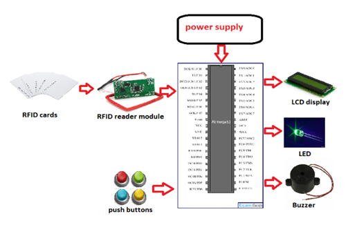
In this study, ATMEGA32A microcontroller, 5v power supply, EM-18(RFID reader module) RFID cards, LCD display, Push Buttons, LEDs, buzzers, resistors and capacitors were used.
Fig.1. Components used for the EVM Creation of a Flowchart for the Voting Process
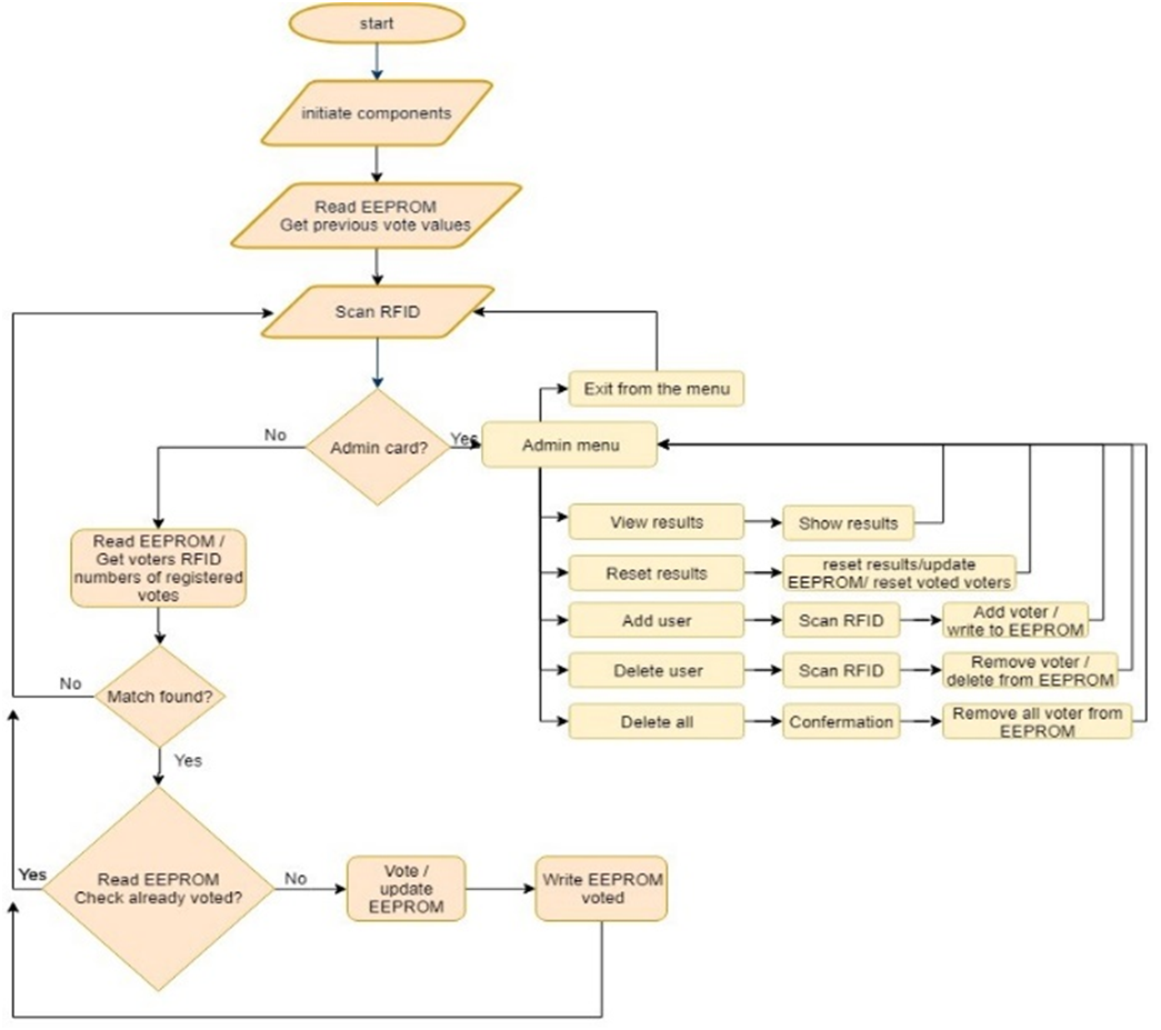
After identifying all the required components, a flow chart was created as shown in Fig.2 for the voting process by considering voter authentication, ballot casting, ballot submission, vote tabulation and results announcement.
Fig.2. Flowchart of the main process in the system
System Design and Development
The microcontroller used in this entire system is Atmega32A and it was interfaced with RFID reader module. EM4100 RFID reader module was used in here to read RFID cards which work at 125 kHz frequency. When a RFID card comes in the range of the reader, the unique data in the card is received by the reader in the form of RF signal. The reader then transmits this data in byte form on its serial transmit pin. In here RFID reader module was connected to Rx and Tx pins in PORTD of the microcontroller. This data can be read by a microcontroller using USART communication or can be viewed on PC terminal.
After receiving the voter ID from the RFID reader, the IC compares the ID and if it’s authorized the voter will get the chance for voting. Buttons were used for incrementing the votes of candidates and for resetting the candidates’ votes to zero. Capacitors were used for nullifying the bouncing effect of buttons and resistors were used to limit the current when the button is pressed to pull down the pin to the ground. Therefore, if authorized voter is pressed the button, the controller picks it and increments the corresponding candidates’ number inside its memory and after incrementing it shows the corresponding candidates score on the LCD display. LEDs and Buzzers are used to indicate the vote casted and to indicate the scanning process of card. In here EEPROM was used to store data. The data stored in the EEPROM will remain even when the microcontroller is turned off. So, it helps to improve the security of the device. The voltage of the power supply given is 230 V and a powerpack is used to convert 230 V to 12 V/ 5 A and it convert to 5 V / 200 mA for microcontroller using 7805 regulator power supply circuit.
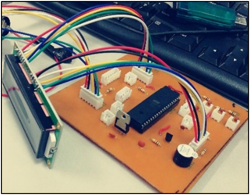
When making this device PCB was designed at first. Proteus was used to draw the schematic diagram and the PCB layout. After making the PCB all components such as LCD, RFID module, push buttons, LED, capacitors, buzzer were soldered and connected using connectors. USBasp programmer was used to program Atmel ATmega 32A microcontroller.
Fig.3. The electronic voting system design with components
RESULTS AND DISCUSSION
Due to the drawbacks of the traditional voting system in Sri Lanka, it is important to introduce a novel concept to improve the election process. Therefore, this study aims to implement an electronic voting system by using RFID technology. At present, this technology is very popular in the world as it is used in many secure systems, such as contactless credit cards and secure entrance systems.
Fig.4. Initial message displayed in the RFID based Electronic Voting System
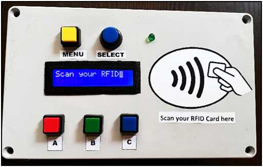
In this RFID based electronic voting system, the voter must have the voter ID with an RFID tag that contains information related to the individual voter when he enters the voting place. The Electronic Voting System displays an initial message as “Scan your RFID,” and then the voter can scan their voter ID as shown in the Fig. 4.
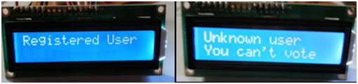
The RFID tag is verified with the microcontroller Atmega32 to check whether the voter can cast his vote or not. If the data matches the already stored information, the information is displayed on the LCD display, and the voter is allowed to cast his vote. If the voter is not authorized, then a message is displayed on the LCD display as “unknown user,” and the buzzer alarm will ring to inform them that the person is not allowed to vote. Fig. 5 represents the messages displayed on the screen for registered and unregistered users.
Fig.5. Messages displayed on the screen for registered / unknown users
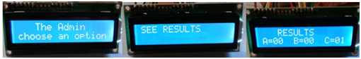
The admin panel has a separate ID, and they have the authority to see the results of the election, to reset votes, to add a new user, to remove a user from the database, or to reset all registered users. In this system, only the vote is saved, and the voter ID will not be recorded. Therefore, even the admin panel doesn’t have access to check which voter votes for which candidate. So that all the votes are confidential in this system. The admin panel options are shown in Fig. 6.
Fig.6. The Admin panel option for see the results of the election
In this study, an Atmega32 microcontroller was used as the main controller. The system includes the RFID module, RFID cards, push buttons, buzzer, transistor, LCD display for displaying different messages, potentiometer, resistors, and capacitors. A potentiometer was used to change the brightness of the LCD display. A busser was used to get beep sounds when scanning an RFID, seeing results, or resetting. Push buttons were used as the menu button, select option button and as three voting buttons. EEPROM was used here so that it is non-volatile type memory, as it holds the data even when power is off. So, if the power goes off while the election happens, it would not be a big issue as all the votes are stored in the internal memory of Atmega32.
There are some drawbacks in this system, such as the fact that if the machine is badly programmed, it may give the wrong results, and hardware problems can affect the machine’s functionality. Necessary modifications can be implemented for the system to minimize those drawbacks and obtain the maximum outcome from this voting machine.
Future scope
There are some future scopes as the system can be implemented by interfacing an external memory for storing the votes to prevent loss of data even if the machine is damaged. Another improvement that can be made to this system is integrating fingerprint matching or a face recognition system, which improves the security of the election process. Alcohol and metal detectors can also be interfaced to the system so that an unhealthy environment will not be created.
CONCLUTIONS
Elections have been conducted worldwide for a long time using the paper-based voting method. Now it’s the time to change the system from Paper-based voting system to an electronic based voting system. This study shows that the implementation of RFID-based electronic voting system improves the efficiency, security, and accuracy of the election process, minimizes the possibility of rigging in elections, and also reduces the probability of causing human error.
REFERENCES
- SurendraRao1. (2019, April). IRJET- RFID based Smart Voting System. IRJET. https://www.slideshare.net/irjetjournal/irjet-rfid-based-smart-voting-system
- Olumide S., A., Olutayo K., B., & E. Adekunle, S. (2020). A review of electronic voting systems: Strategy for A novel. International Journal of Information Engineering and Electronic Business, 12(1), 19–29. https://doi.org/10.5815/ijieeb.2020.01.03
- Chowdhury, L. H., Shithil, S. M., &Waishy, M. T. (2022). Secure and reliable election process to stop vote rigging and tampering. International Journal of Advanced Networking and Applications, 13(04), 5076–5080. https://doi.org/10.35444/ijana.2022.13410
- A, A., P, S., A, J., P, U., & K, K. (2021). RFID based Smart Electronic Voting System for reducing electoral frauds using Arduino. International Journal of Electronics and Communication Engineering, 8(4), 22–25. https://doi.org/10.14445/23488549/ijece-v8i4p105
- Saad, A., Roseli, M. I., &Zullkeply, M. S. (2014). A smart e-voting system using RFID authentication method for a campus electoral. Proceedings of the 8th International Conference on Ubiquitous Information Management and Communication. https://doi.org/10.1145/2557977.2557985
- Shaik1, J. B. (2014, June). Voter identification and detection system using RFID andGSM to stop rigging in the elections https://ijireeice.com/wp-content/uploads/2013/03/IJIREEICE1B-s-jani-Voter-Identification.pdf
- Praful Ranjan. (2015, January). (PDF) design of RFID based electronic voting machine https://www.researchgate.net/publication/319351144_Design_of_RFID_based_Electronic_Voting_Machine_RFID_based_Electronics_Voting_Machine.